Teaspoon Telegraph Manual
Up: teaspoontx
Introduction
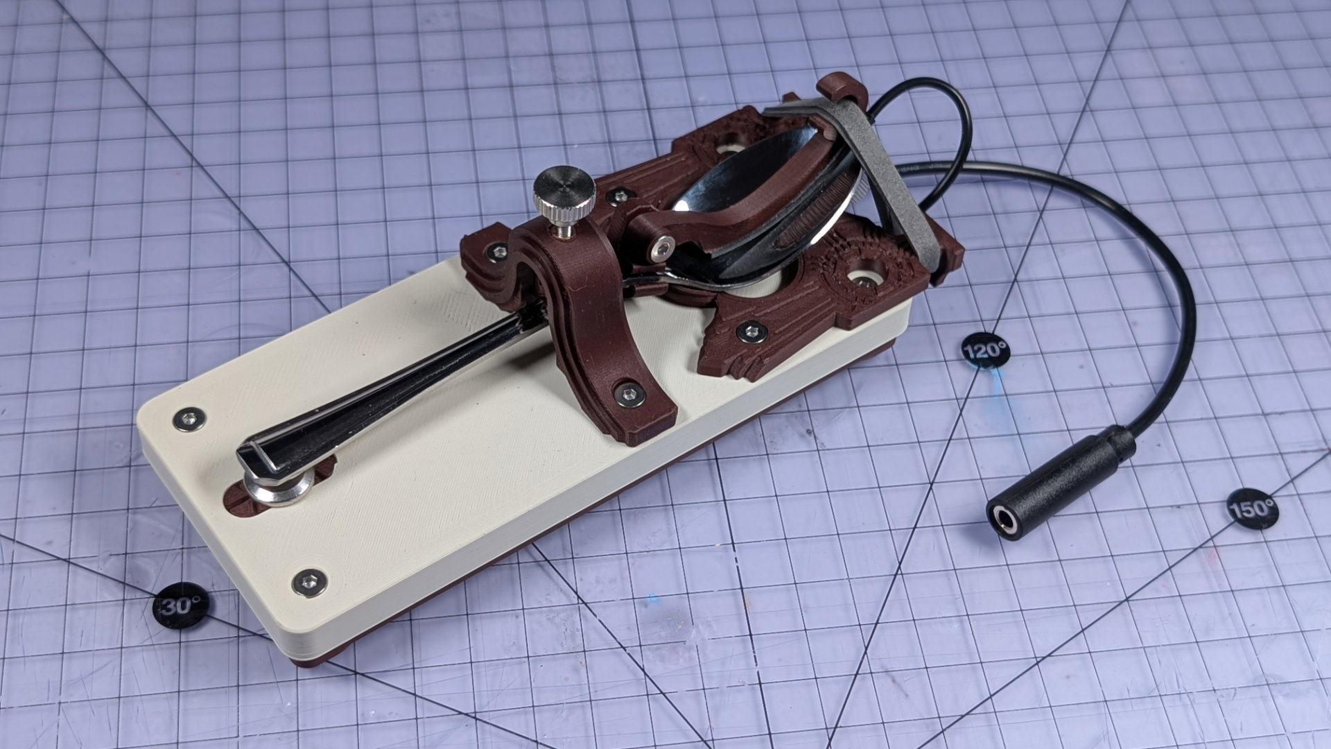
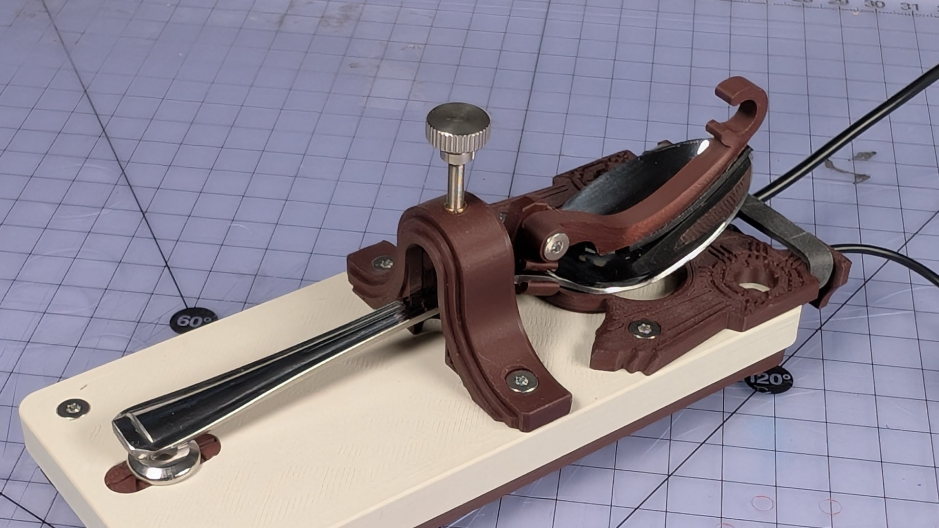
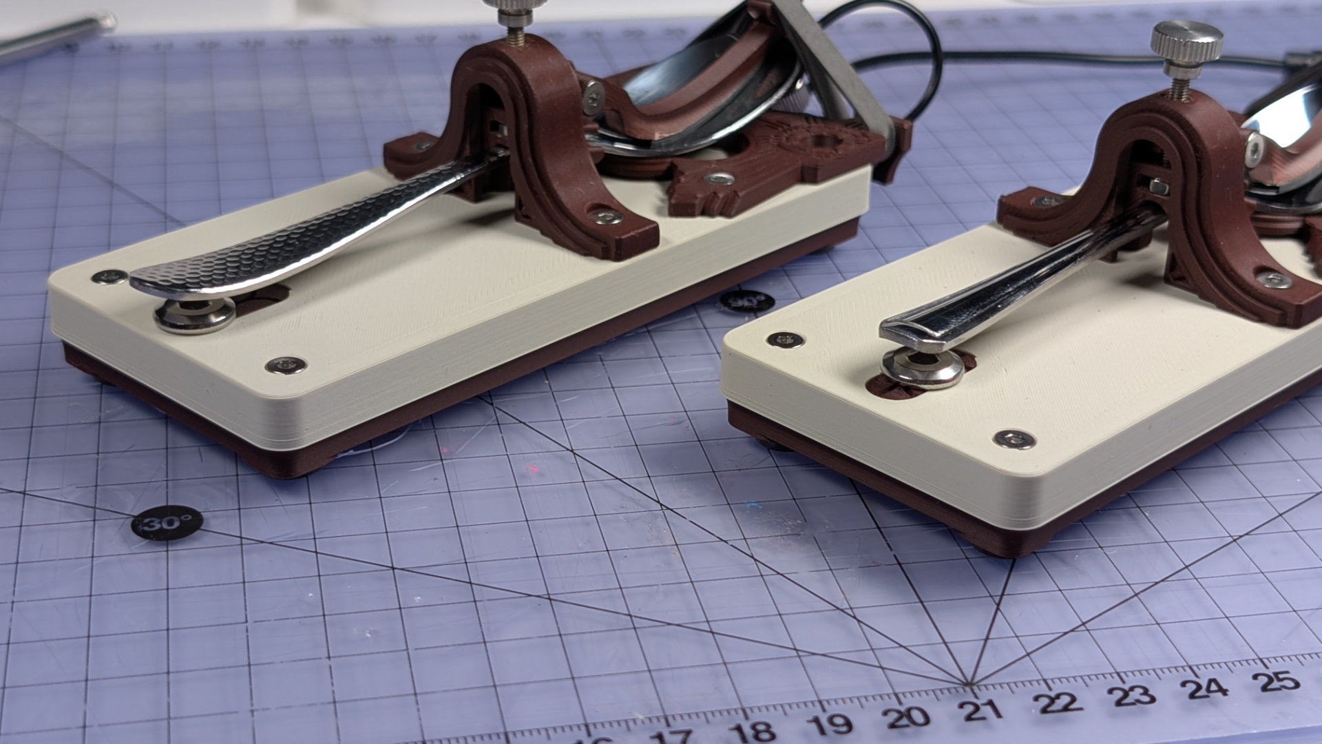
The Teaspoon Telegraph is a 3D printed straight Morse key, designed to work with most teaspoons. It might not be a fine Morse key, but was designed to be inexpensive and customisable, while feeling nicer to use than most fully 3D printed ones. It uses a conductive spoon as the lever-arm, with a bearing surface under the head of the spoon providing sliding contact points, and an elastic band as the spring.
This manual is simply an orientation showing how to use, adjust and maintain one.
Parts
Main Components
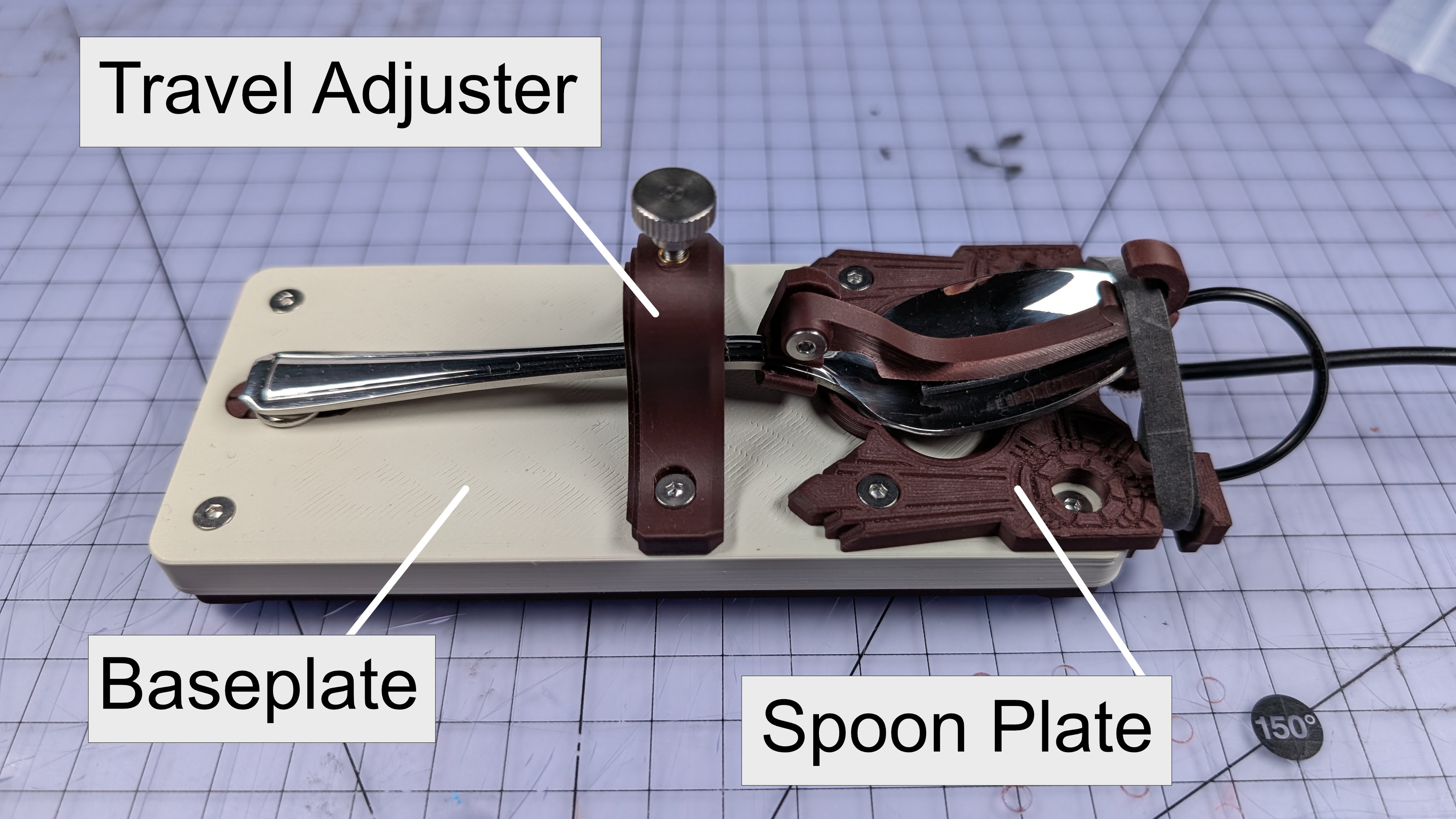
- Baseplate
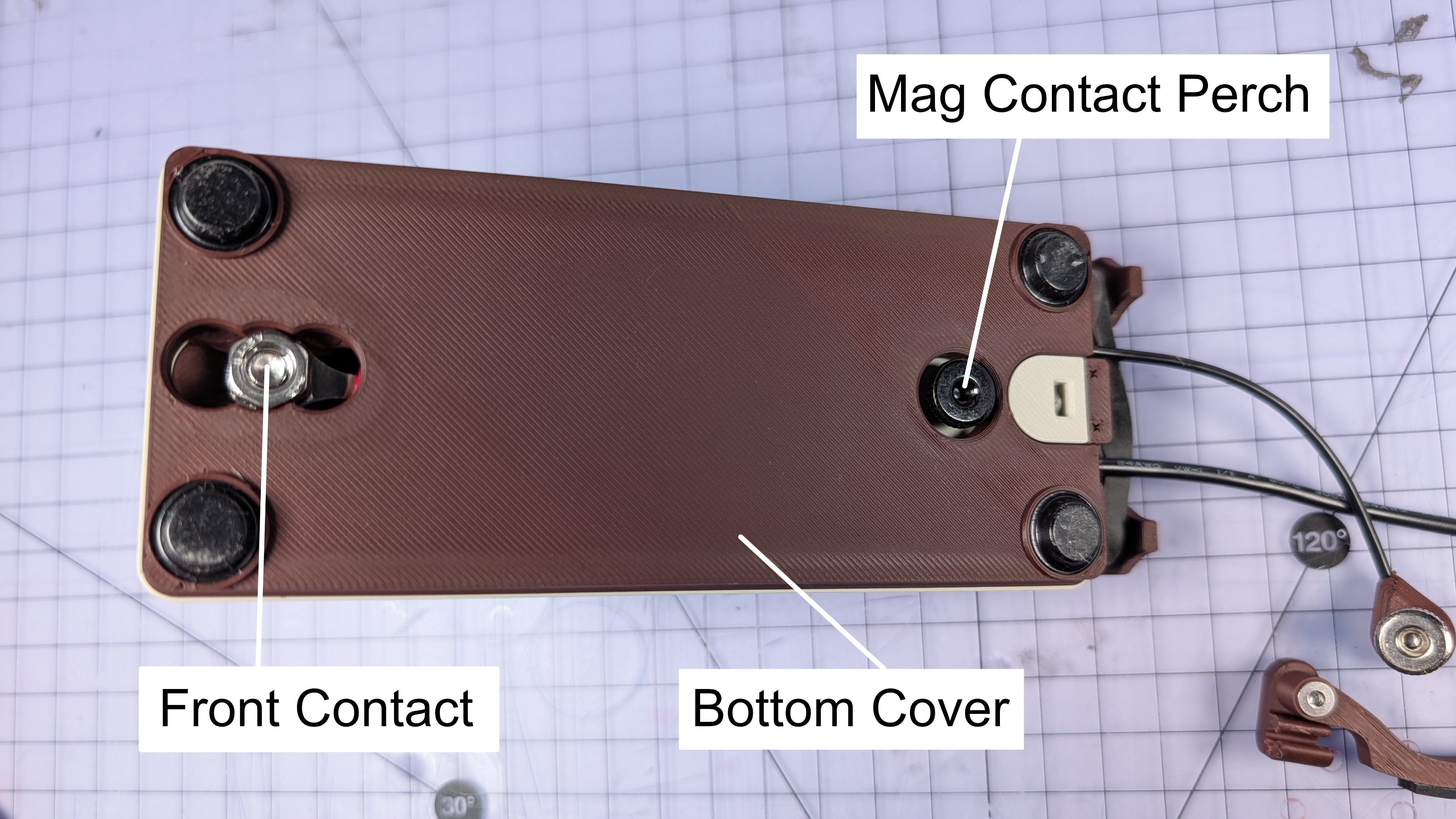
- Bottom cover
- Travel adjuster
- Spoon plate
Smaller Components
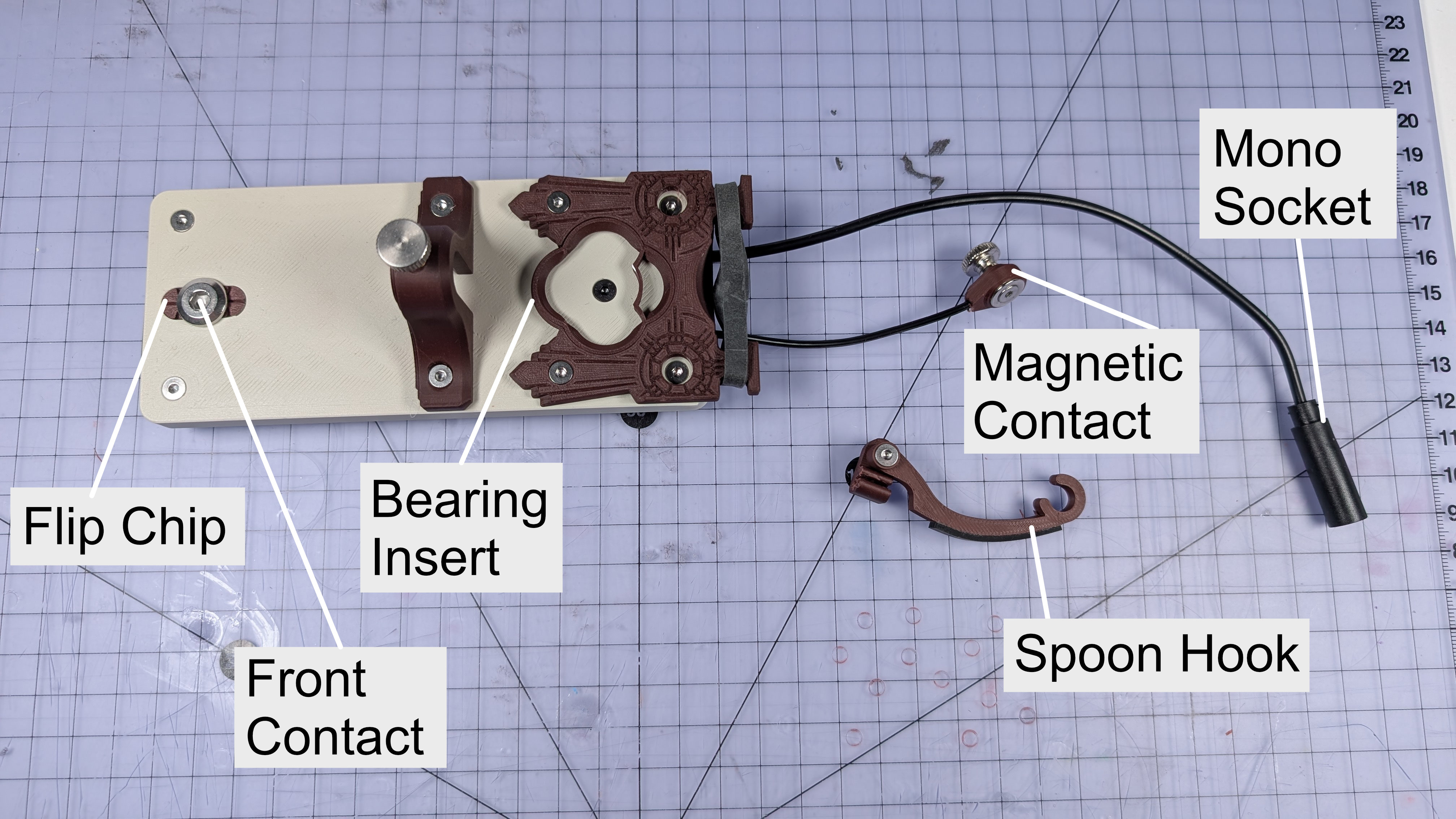
- Bearing insert
- Front contact
- Flip chip
- Magnetic contact
Fixings
- M3x12mm countersunk machine screws (every fixing is this size, except the two below)
- M3x20mm knurled thumbscrew (for travel adjuster)
- Two M3 knurled thumbwheels (for mag contact and parking)
- One M6x12mm bolt (front contact)
- M3 hex nuts or brass inserts, depending on how yours it built.
None of the fixings on this require high amounts of torque. Particularly with the M3 ones, gently hand tightening them is more than enough.
Spares & Interchangeable Parts
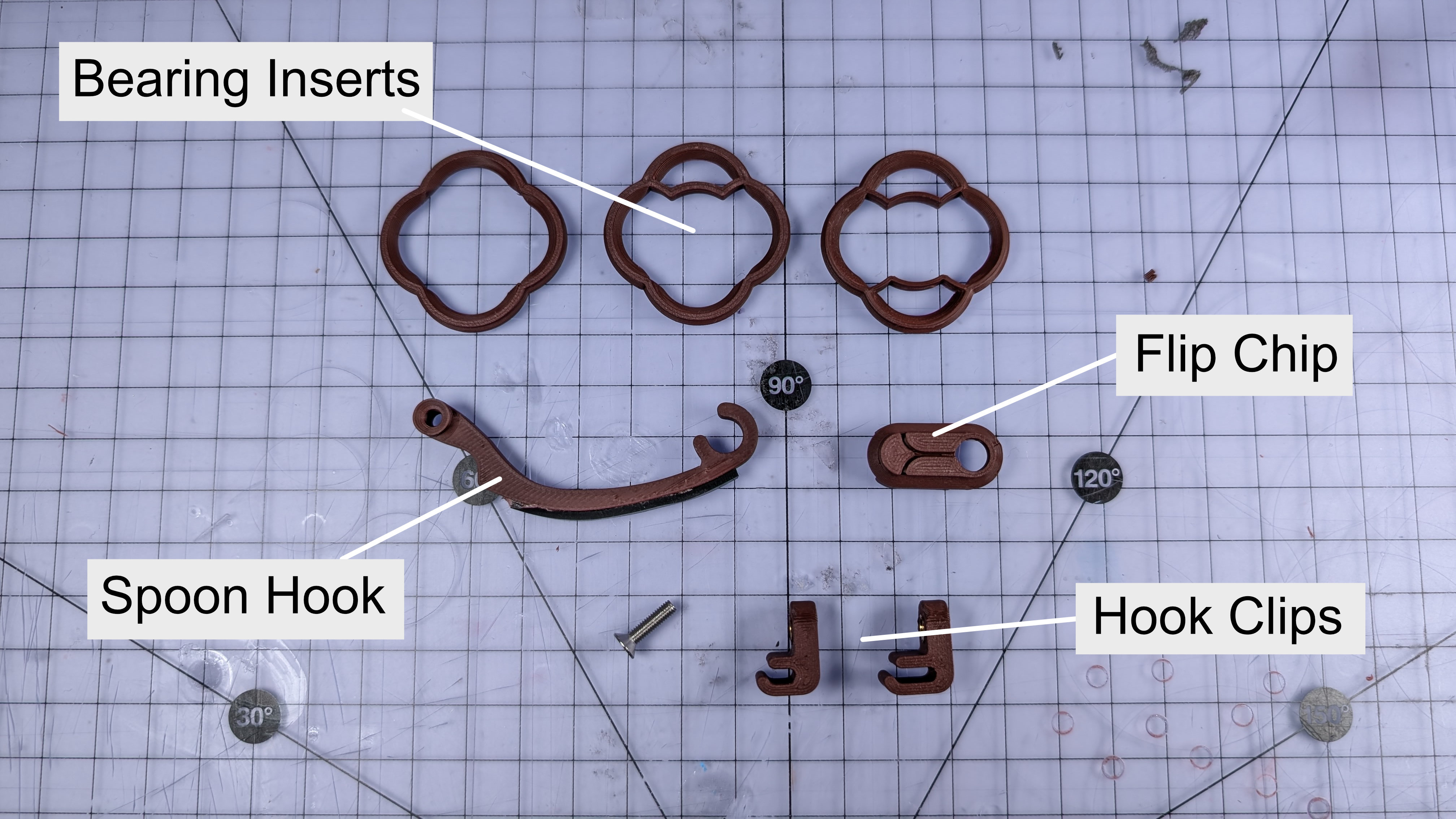
- Bearing inserts
- Short hook
- Long hook
- Spoon clips (narrow, wide)
- Flip chips
- Elastic bands (size 64)
Tools You Might Need
- 2mm hex driver
- 4mm hex driver
- 10mm wrench
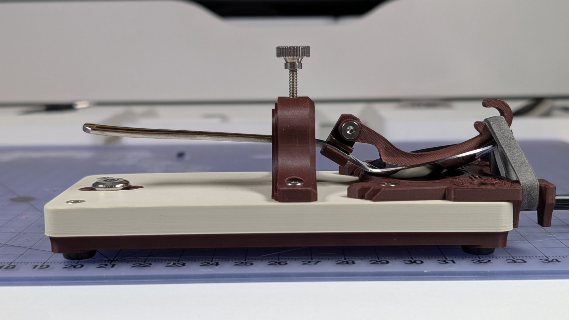
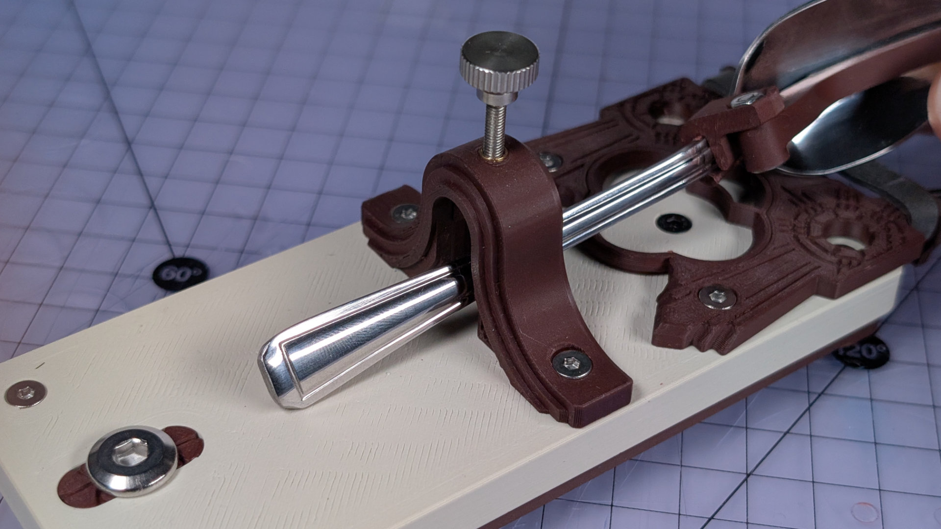
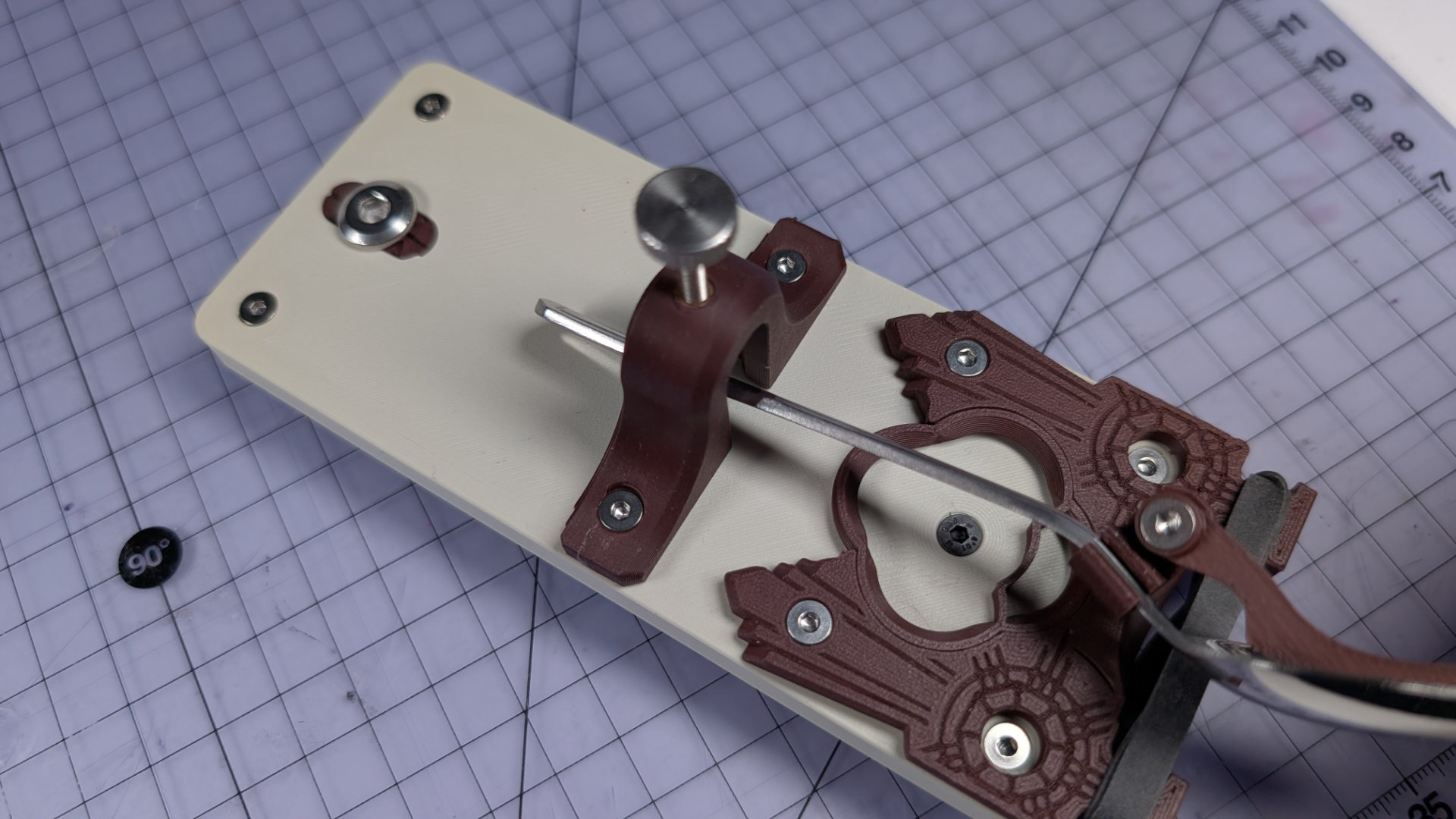
Travel Adjust
The travel adjustment dictates the gap between the spoon and the front contact. Lower tends to be better, depending on the spoon.
At higher distances, the lever-arm motion depends on the spoon back sliding over contact points on the bearing surface. At shorter gaps, the motion switches to using the spoon as a flexture, which gives a much more consistent feel. I find a gap of 0.5 - 1.5mm tends to be best.
Should you need to remove or replace the travel adjuster, it's secured with the two M3x12 screws either side. When replacing it, be very careful not to over-tighten these, as they could force the 3D print layers to separate, damaging the part. I find a screwdriver-type hex tool is just right for this, whereas a right-angled hex key can easily apply too much force.
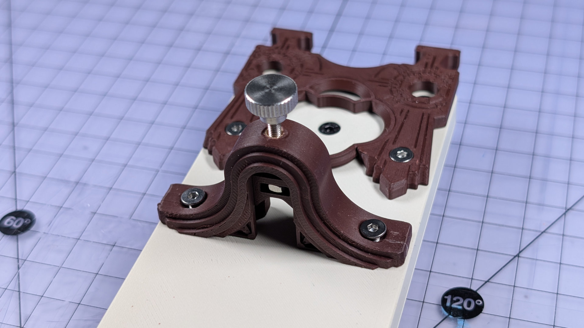
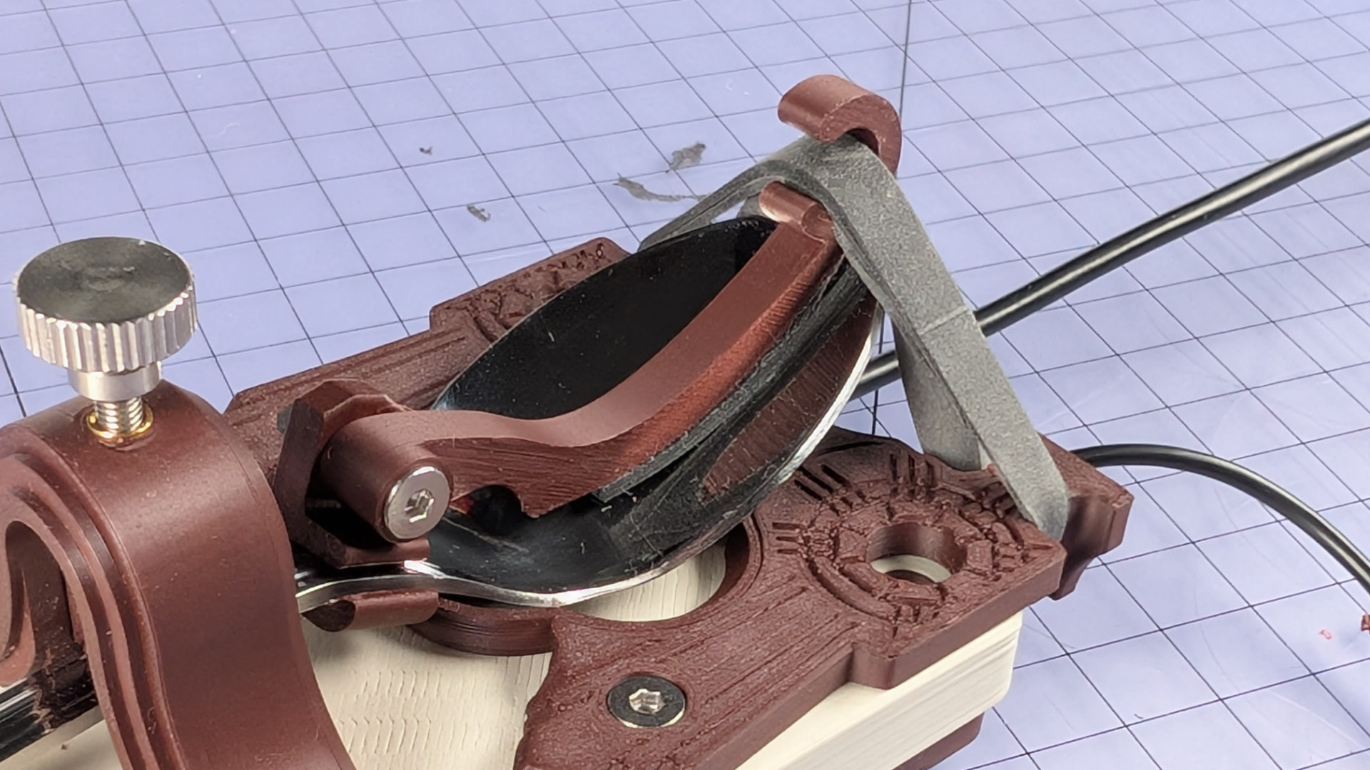
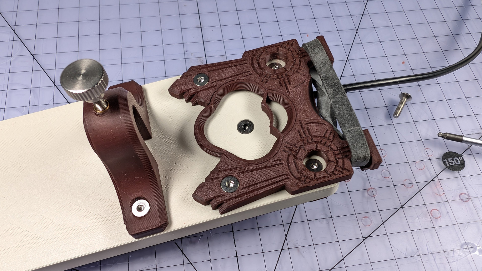
Magnetic Contact
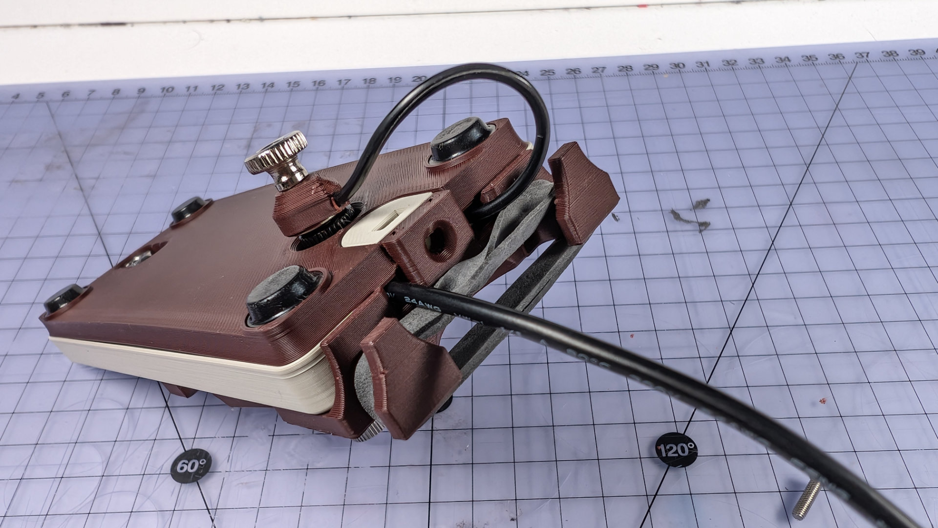
At the back of the key, the spoon plate has a rounded cutout to expose more of the spoon. This is clearance for the magnetic contact, which is placed on the underside of the spoon. When the lever-arm is pressed onto the front contact, it completes the circuit.
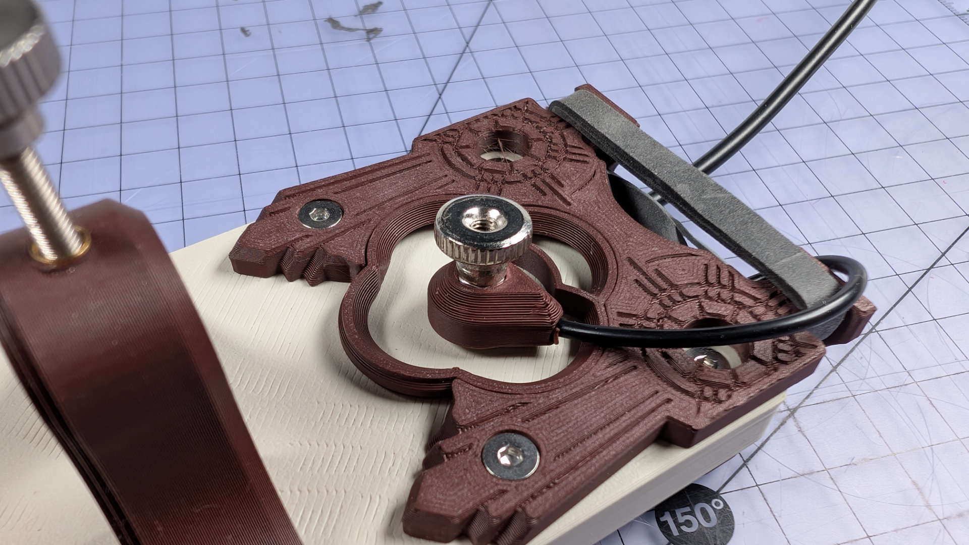
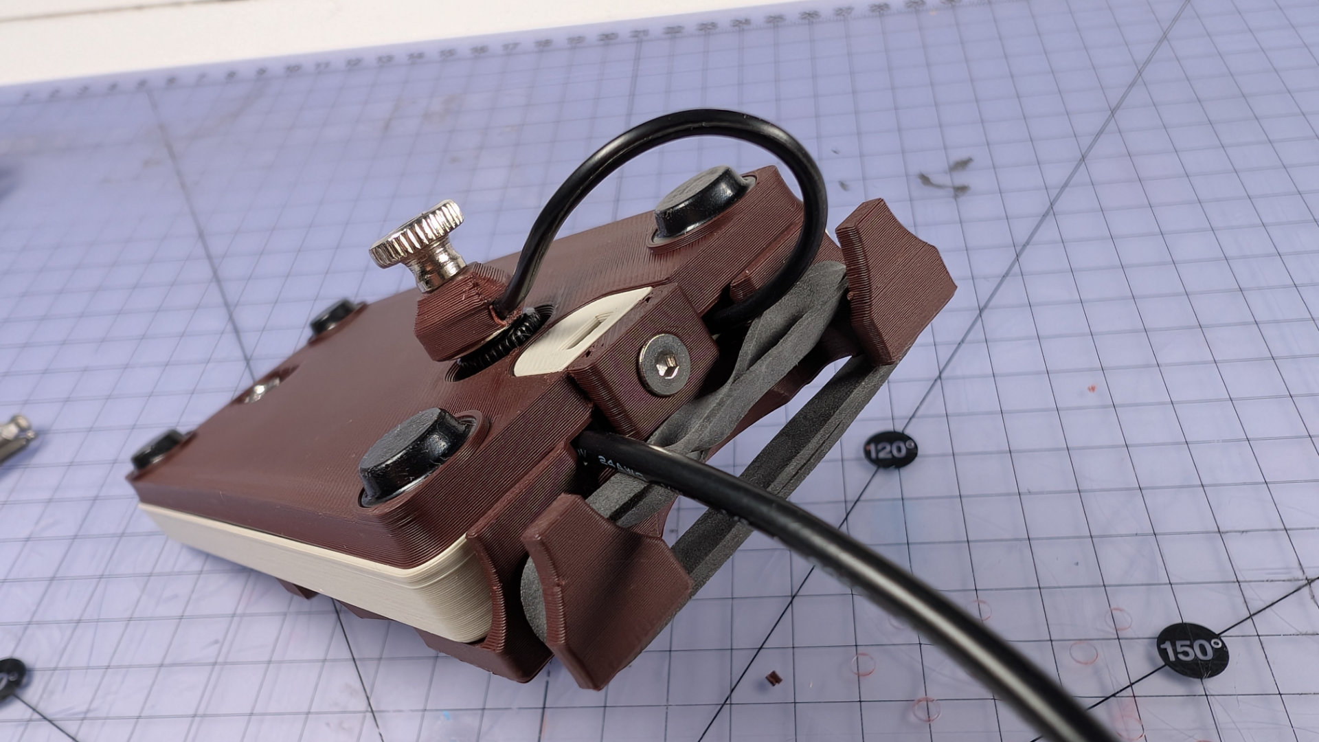
There are also two places to park the magnetic contact. This is useful if you're building or working on the key, as it keeps the magnet away from your screwdrivers. One of the parking places is on the underside:
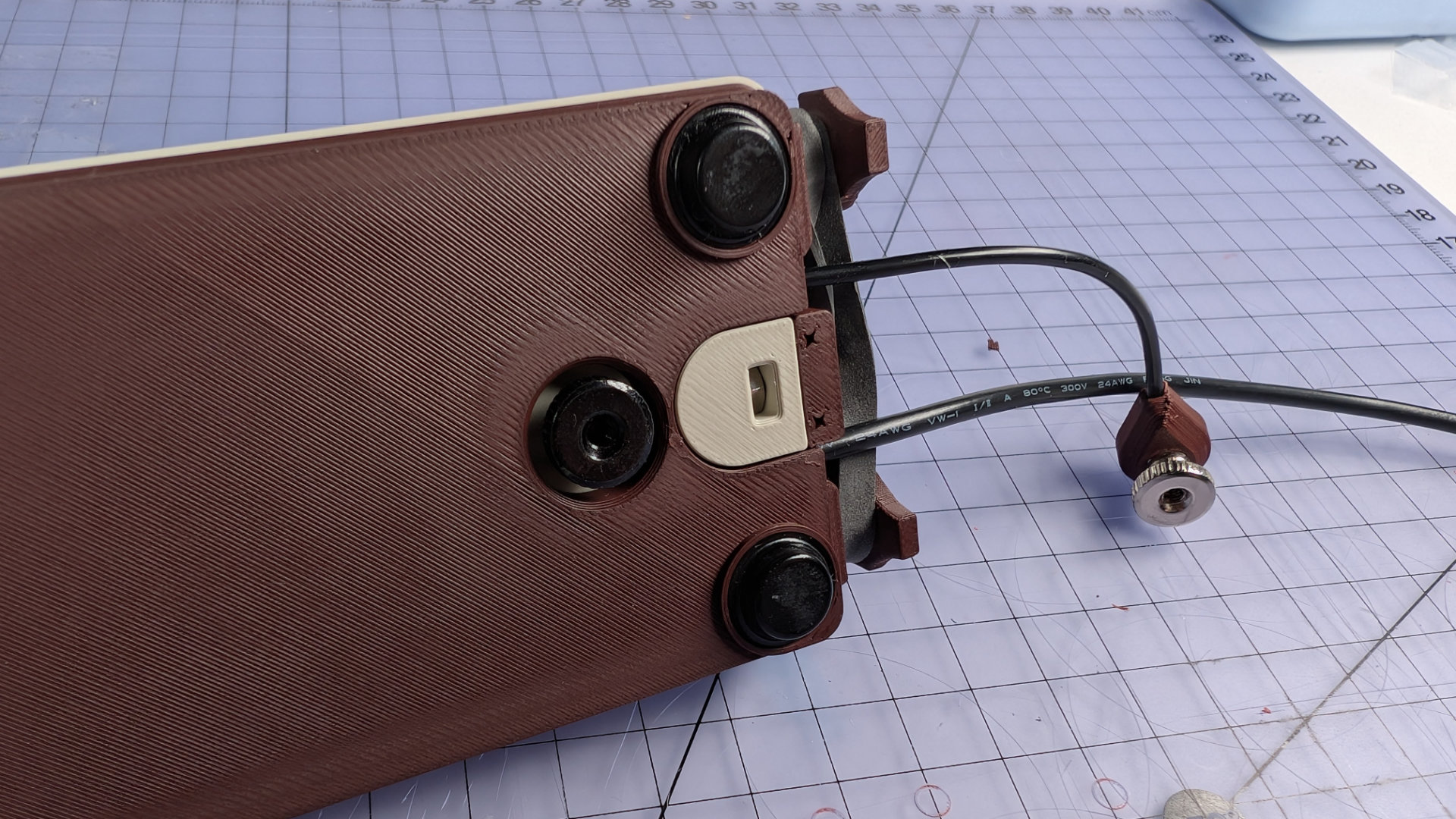
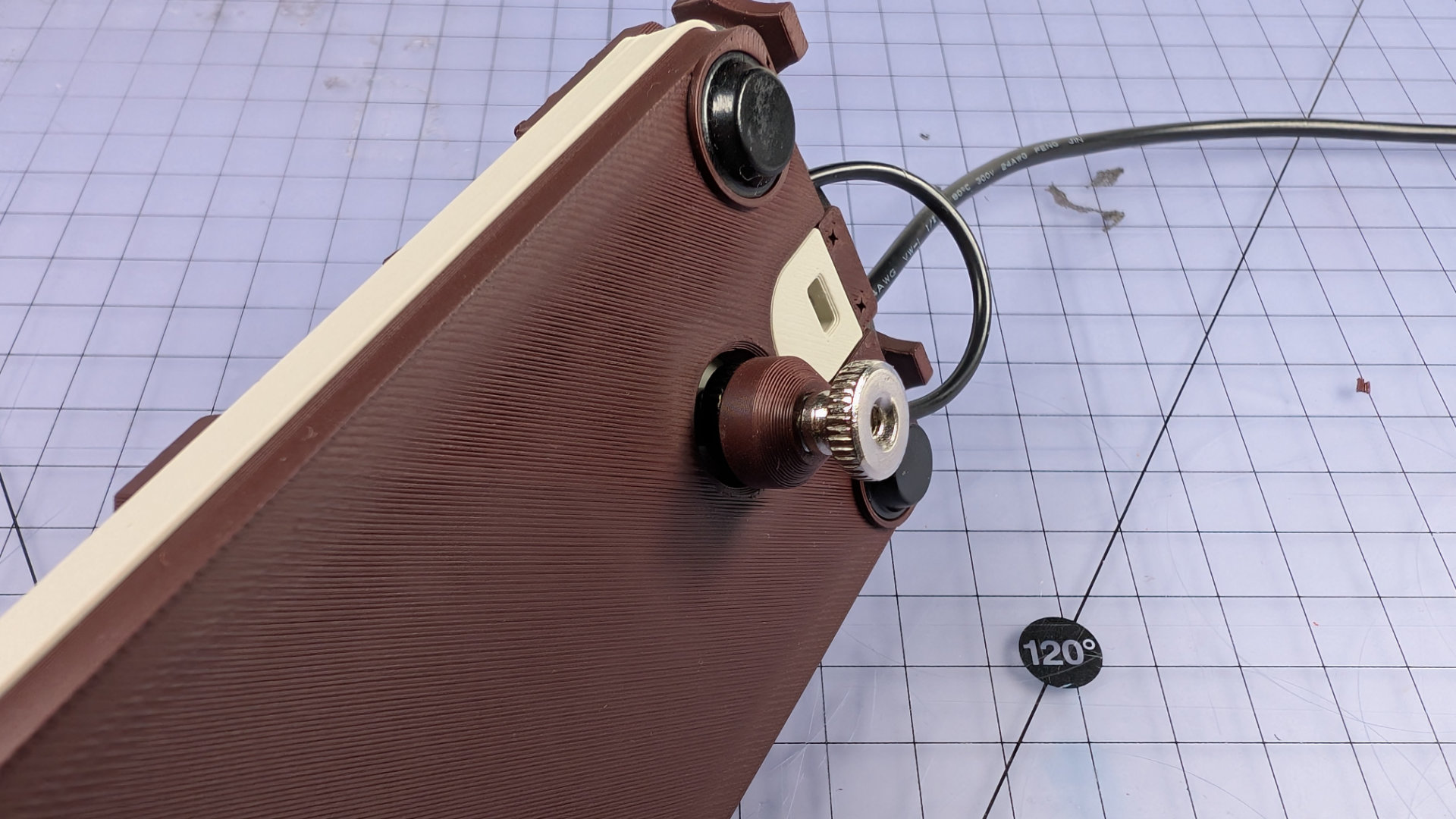
That's useful if you're doing anything that involves removing the spoon plate.
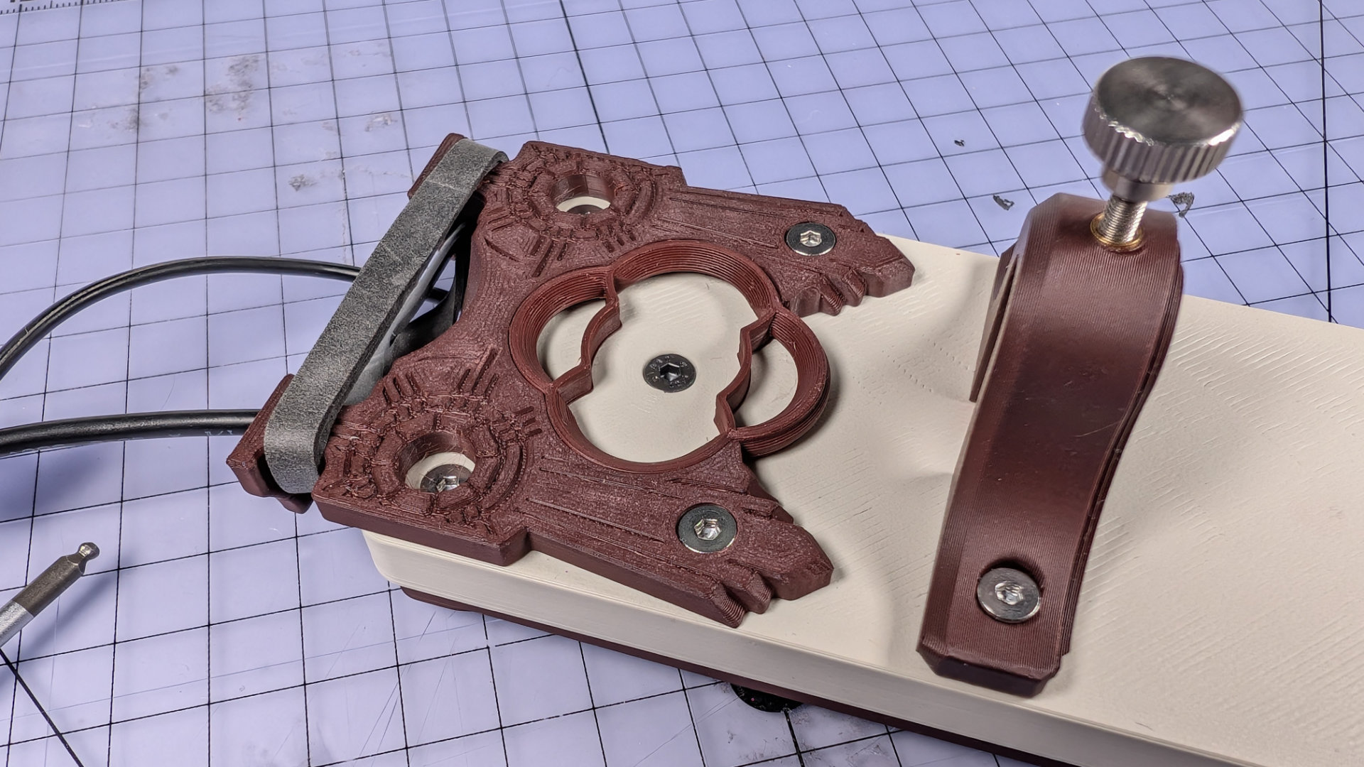
The other is the corresponding fixing up top, in the middle of the bearing insert. This means that even if there's no spoon, you can still keep the magnet out of the way while removing the baseplate.
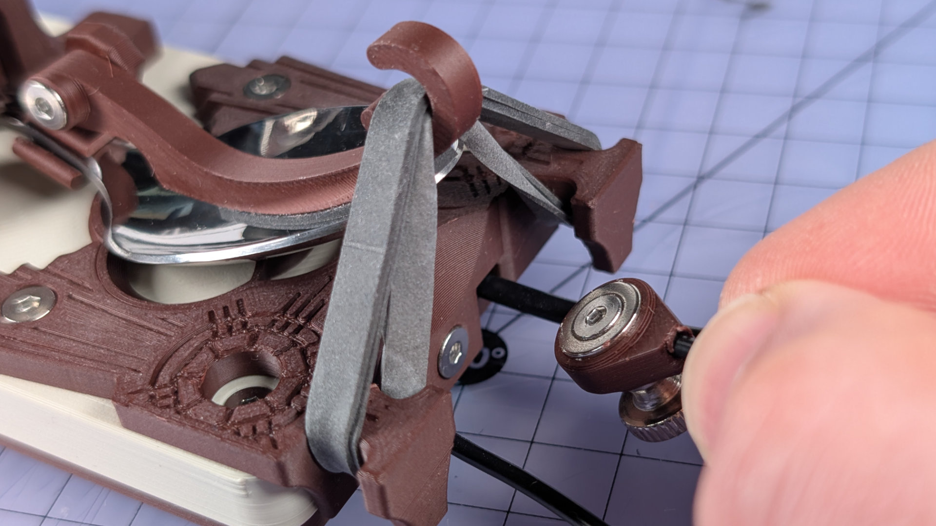
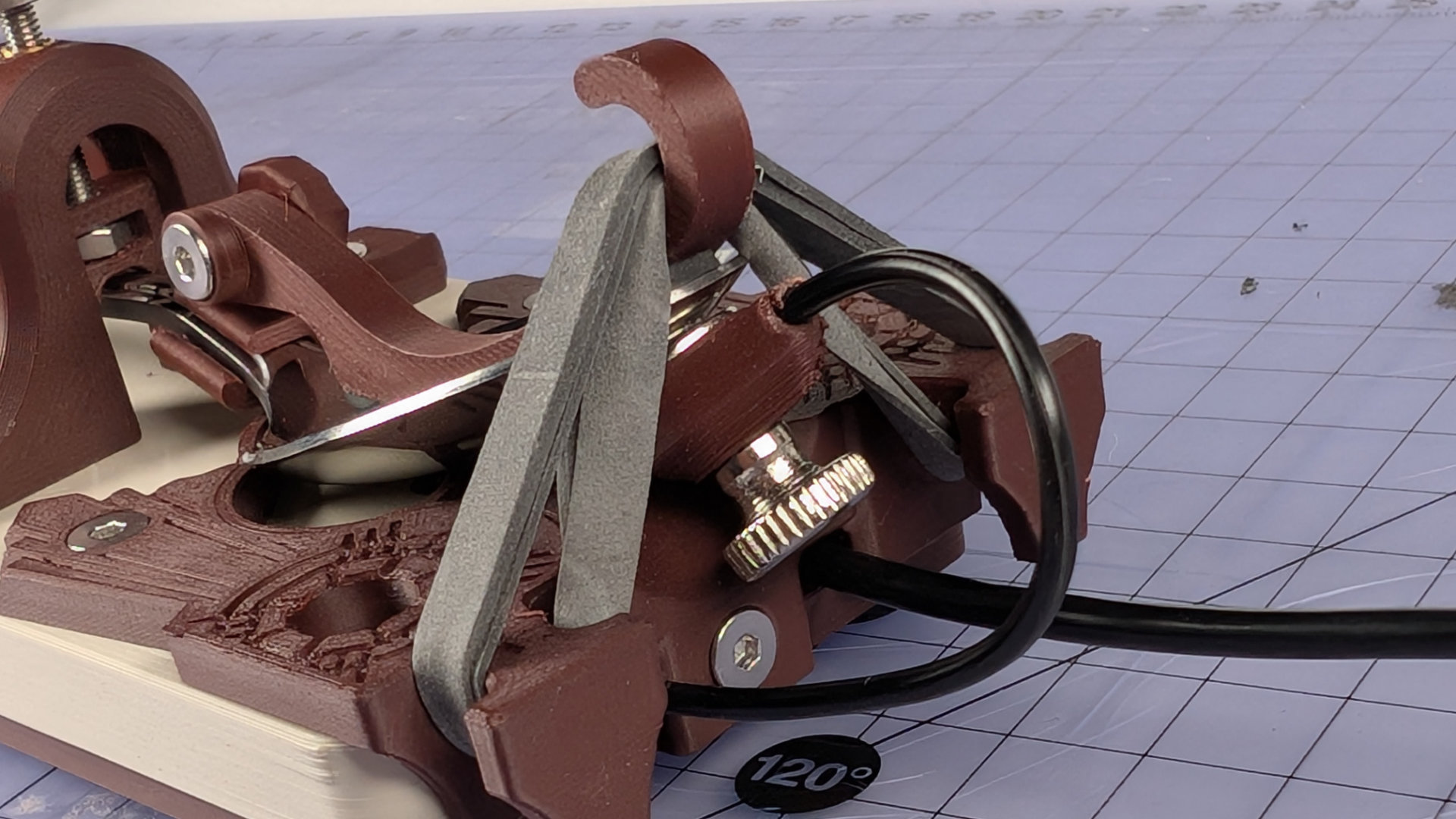
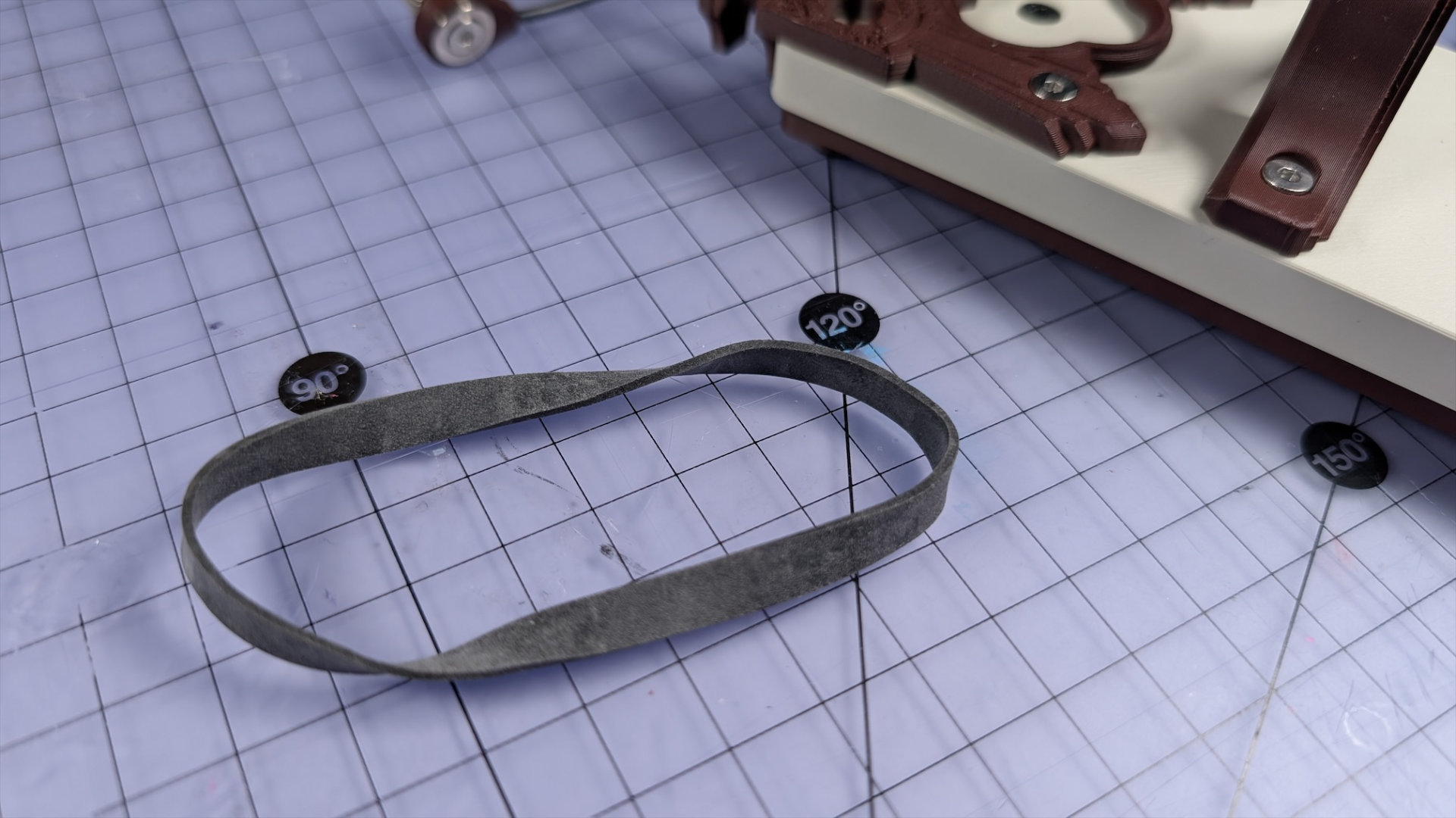
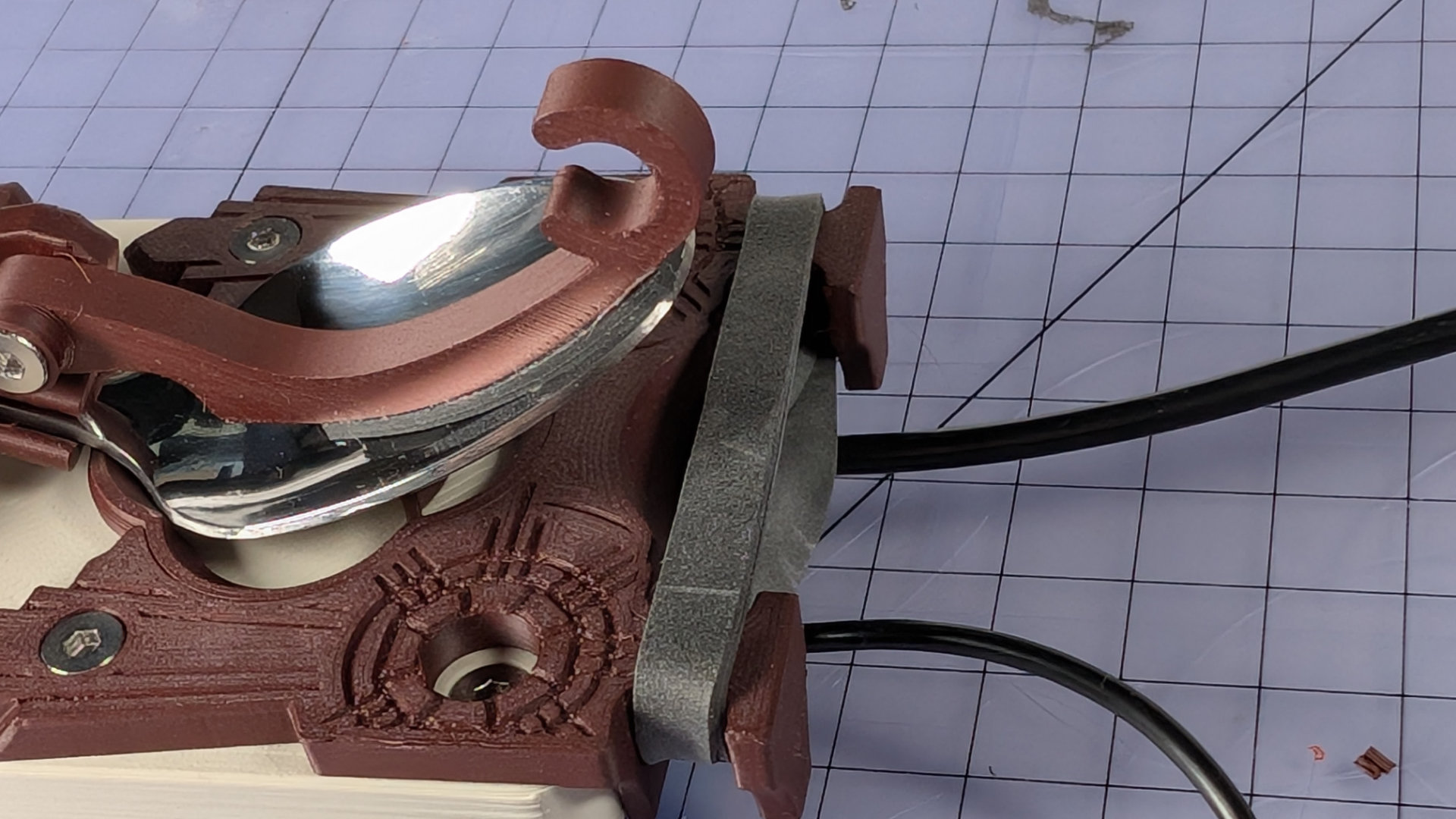
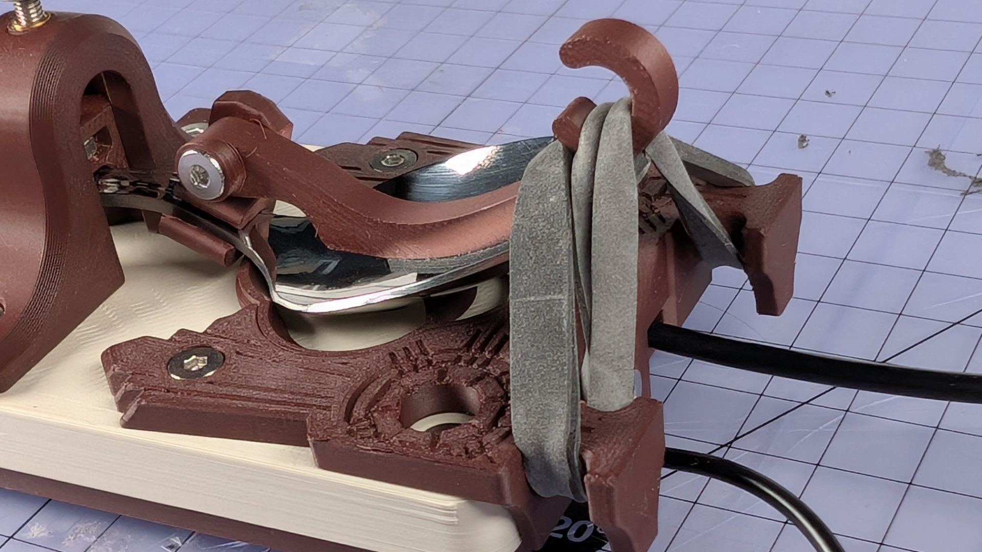
Elastic Band
The key is designed to work with a size 64 elastic band; 87mm by 6mm (the black ones shown here were a custom order). Other sizes of band will work too.
Doubling the band up before hooking it onto the spoon plate means it can provide plenty of spring tension.
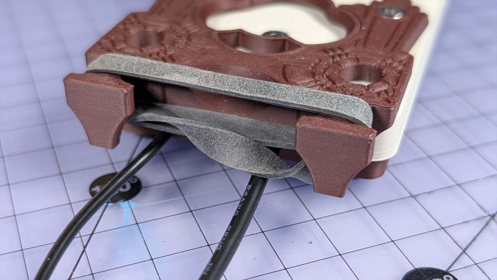
Aligning the topmost sides of the band (as in the photo above) and putting the twists underneath will help it to look neater in use.
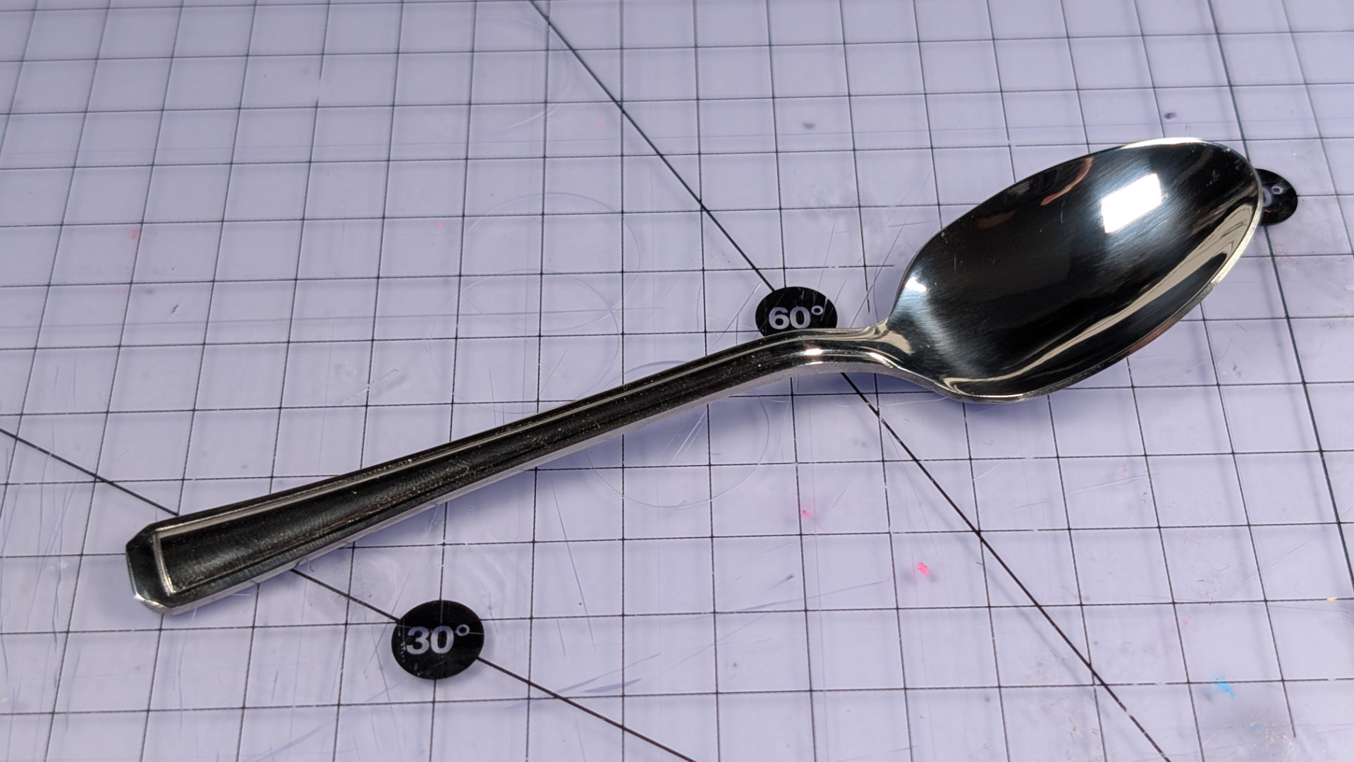
Spoons
The spoon is constrained by three parts to make it work as a lever-arm:
- Hook
- Bearing Insert
- Travel adjuster
All three can be altered to accommodate different shapes and sizes of teaspoon. Some spoons give better feel than others. During prototyping, Alex Johansson commented to me that a hammer textured spoon I gave him significantly reduced fatigue in his fingertip!
In testing, most spoons I've been able to get hold of have worked with the parts I've designed. Not all spoons will work though. Probable failspoons:
- Less than 130mm long: might not reach front contact.
- Necks wider than 10mm: travel adjuster would need more clearance.
- Thick handle profiles: the travel adjuster and spoon clip are designed to work with flat handles. Shaped handles and necks (e.g. with a round cross section) may need different spoon clips or travel adjust padding.
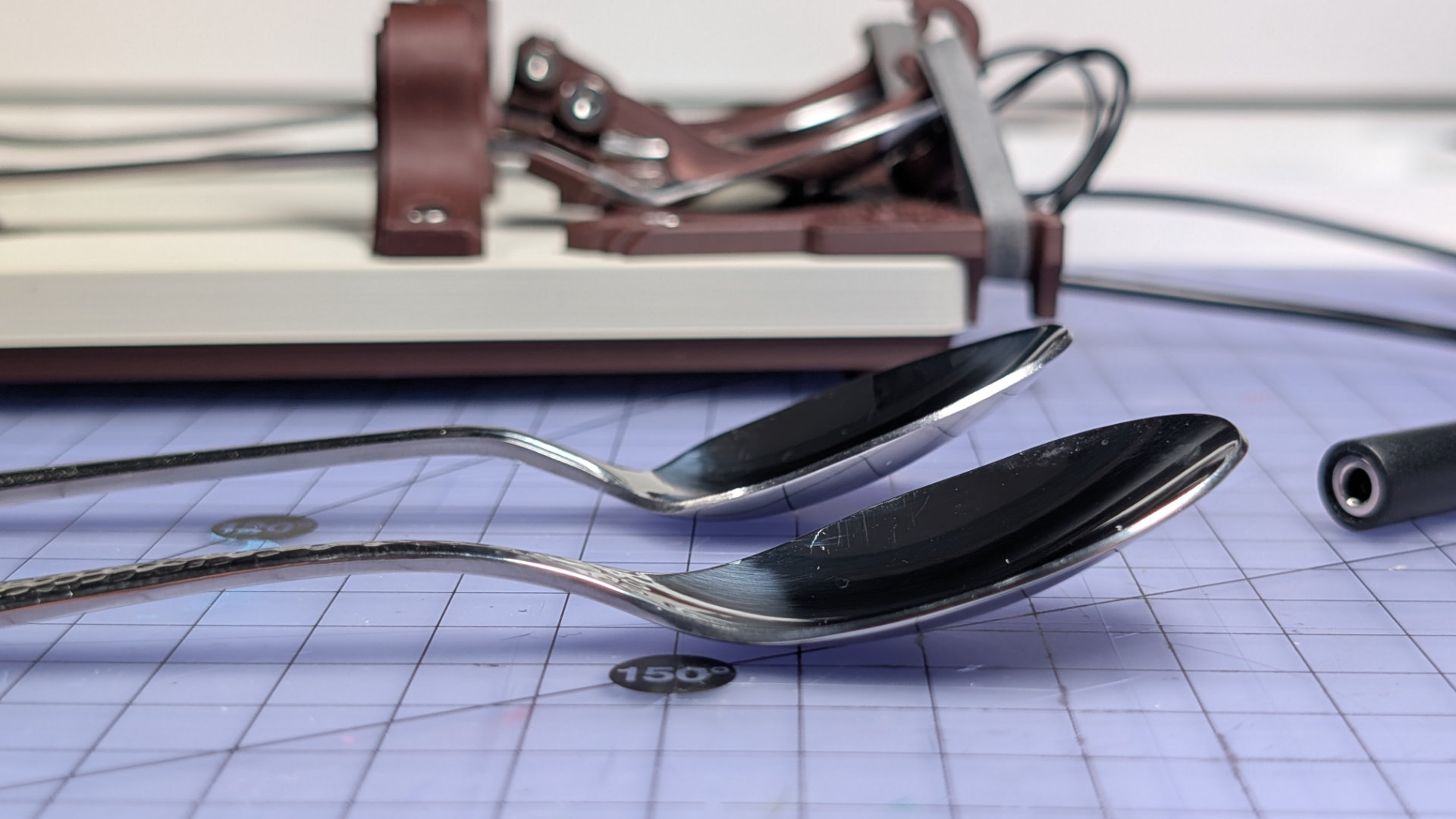
A spoon more than 150mm long might work, e.g a coffee spoon, but will project over the front of the key. This might suit you, but I've found they have too much flex for my liking. Generally, having the end of the handle directly over the front contact, with a small gap, tends to give the best feel.
Spoon Removal
To remove a spoon from the key, first remove the elastic band from the hook. It's easier to do this in two stages than all at once.
Next, open the travel adjuster enough to allow the spoon handle to pass. It should side out through the opened travel adjuster. For very wide, flared or ornate-handled spoons, you may have to remove the travel adjuster from the baseplate.
If you need to use the same hook for a different spoon, push the spoon clip off the neck until it pops free.
Spoon Insertion
First, build the right hook for your spoon: long or short hook, wide or narrow clip; then pop it onto the spoon (see "Spoon Hook", below).
Next, open the travel adjuster fully and slide the spoon in. If the end of your spoon handle is especially wide, as some ornate spoons are, you might have to remove the travel adjuster instead.
Rest the head of the spoon on the bearing surface.
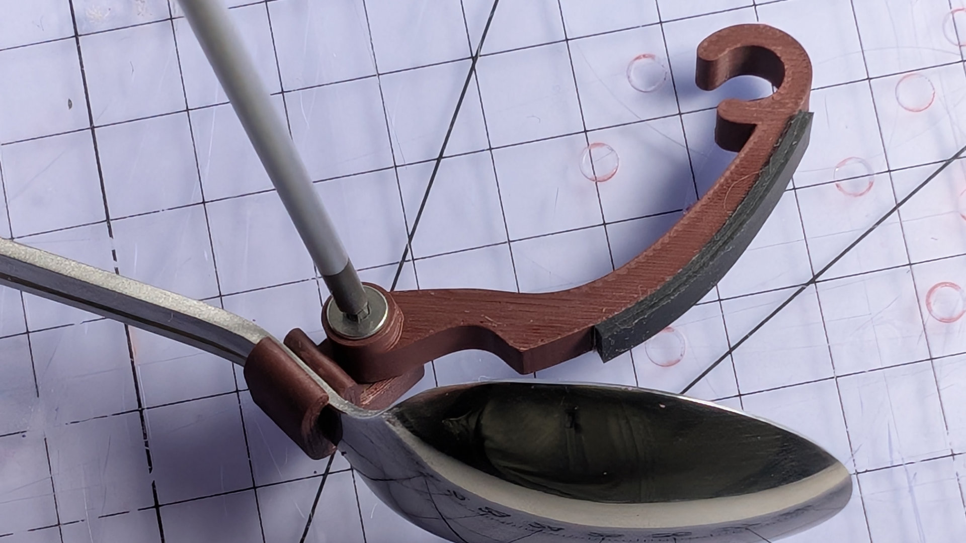
The hook has two stages, making it easier to install the elastic band neatly. First lift the upper spans of the elastic band over the hook, and place them in the outer position like so, outside the C-shaped hook end:
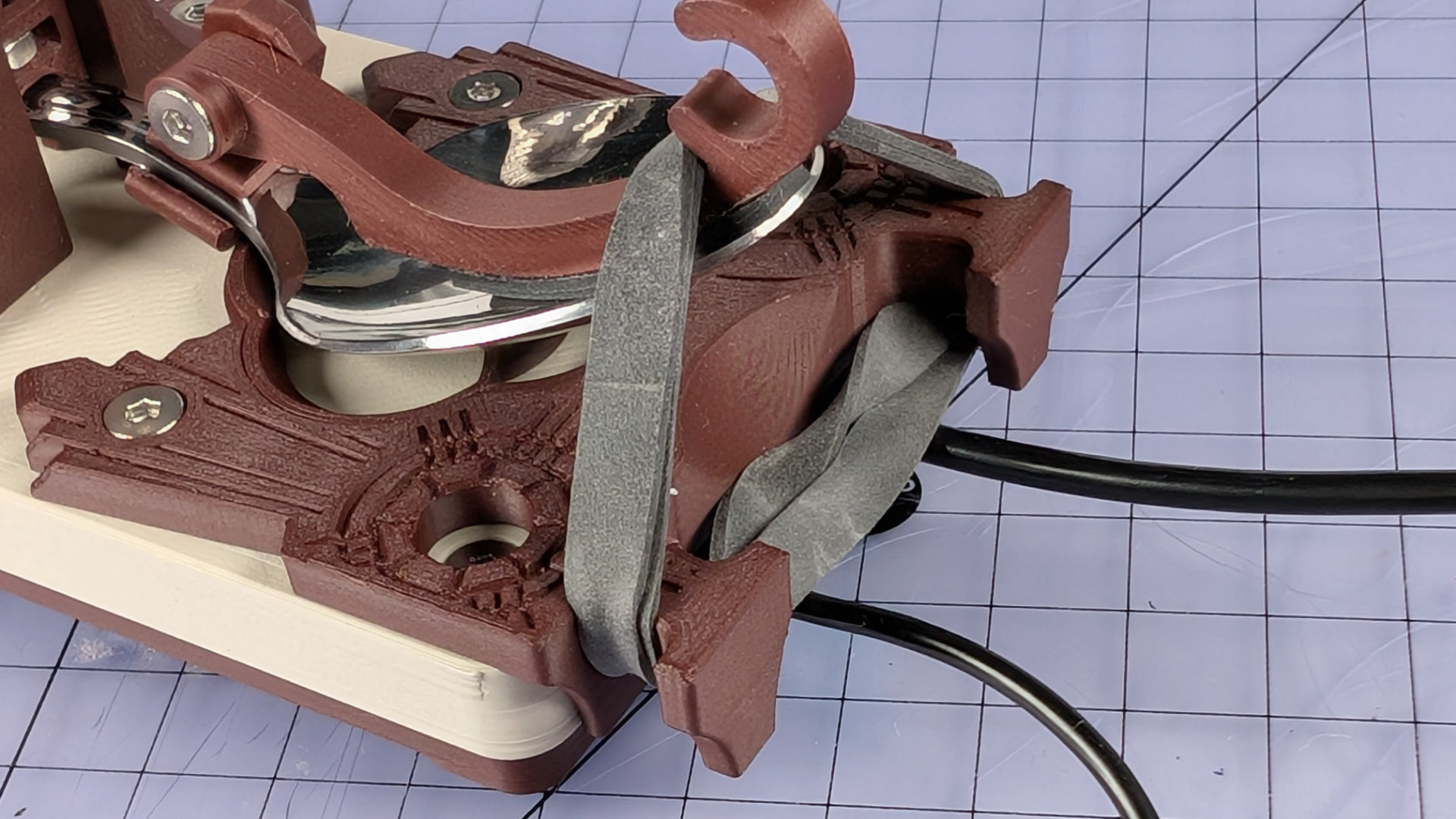
If the lower parts of the band are very tight at this point, you can pull on the outside of the band, either side of the hook, to create more slack. Pull the lower parts up over the end of the hook, and place them inside the C.
Now lift the upper section of the band and place it in the C, over the lower parts. You can pull the sections of band either side of the hook, and underneath the spoon plate, to even up the tension.
Using a larger than needed band, doubled up, also means you can reduce the spring tension by engaging fewer loops on the hook.
Finally, adjust the travel to your liking.
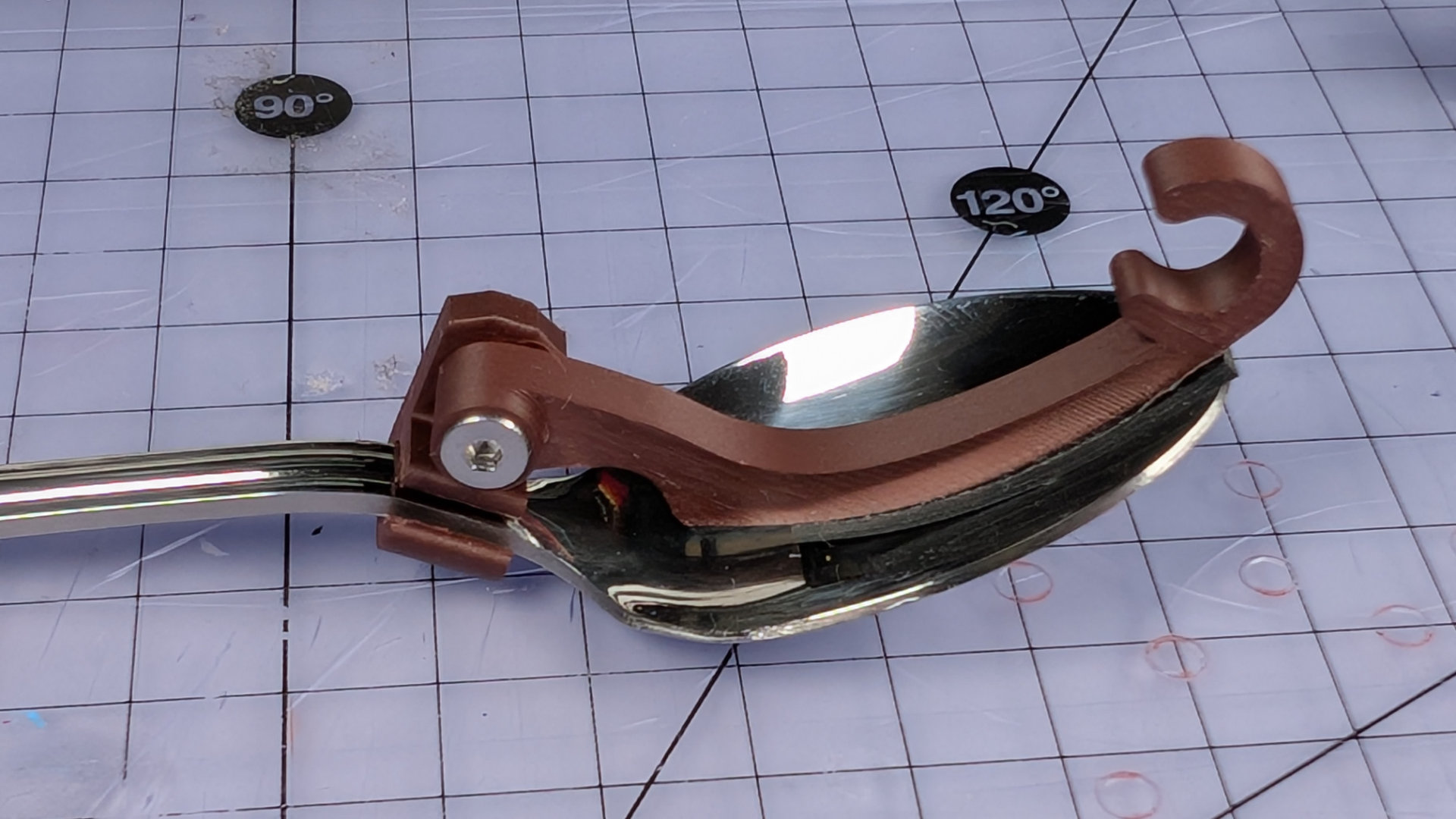
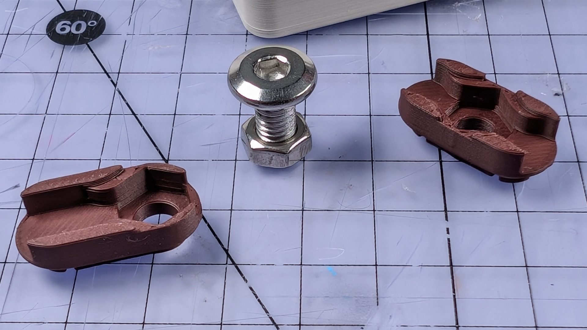
Spoon Hooks
There are two lengths of hook in the kit, designed to suit different shapes of teaspoon. The hook is attached to a spoon clip, which goes over the neck of the spoon. The clips also come in two widths, to suit different necks.
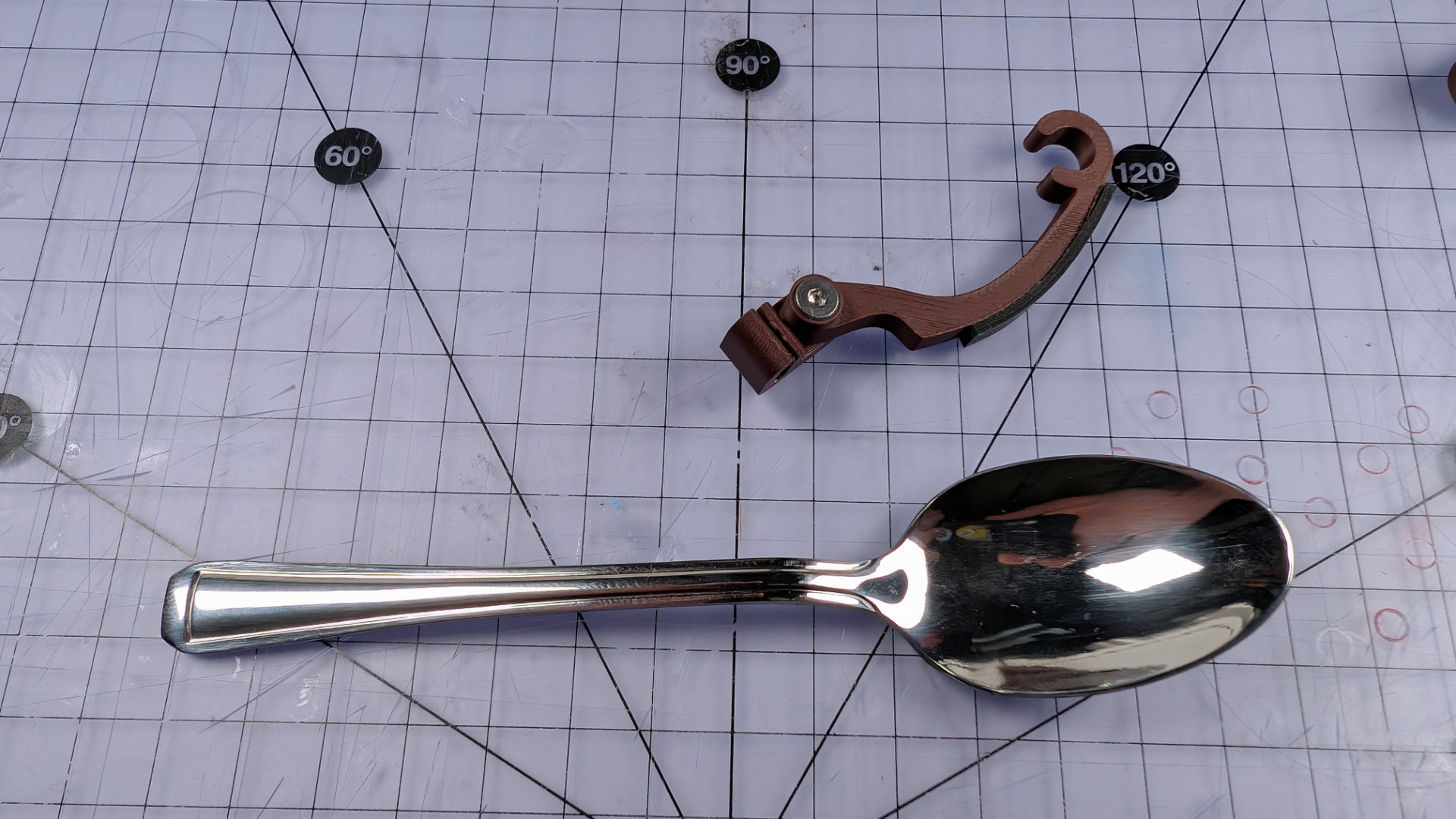
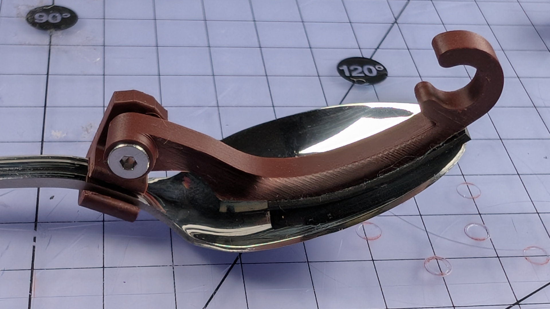
When assembling a spoon hook, tighten the bolt, but position the hook pointing up relative to the clip rather than forwards.
Push the clip over the neck of the spoon until it pops into place. If printed in the correct orientation, it will have enough flex to do this.
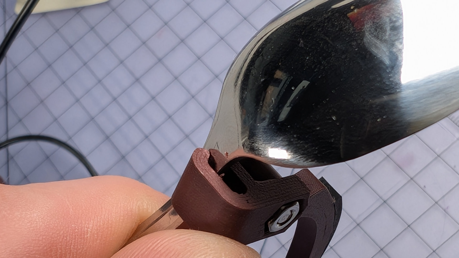
Position the hook so it's sticking up, then tighten the bolt fully.
Now, when you swing the hook down into the bowl of the spoon, it will rotate in a direction that tightens the bolt, keeping things snug to stop any unwanted rattle or movement. If necessary, slide the hook and clip backwards and forward until they sit comfortably.
Front Contact & Flip Chips
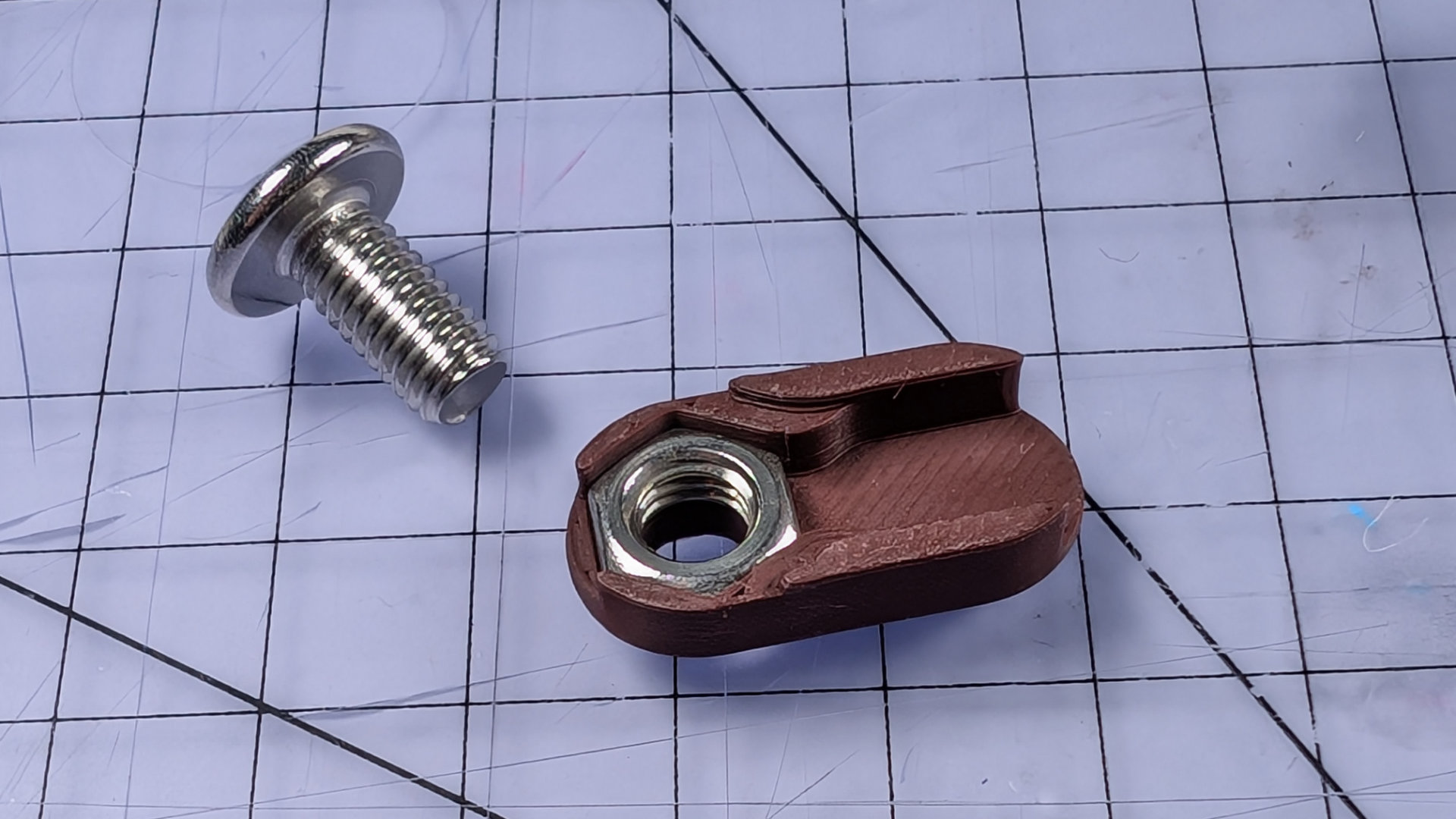
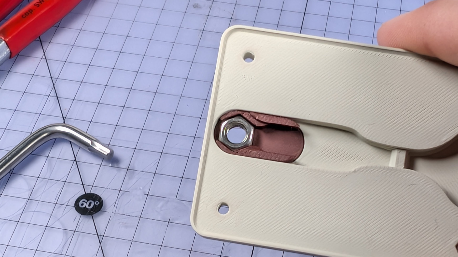
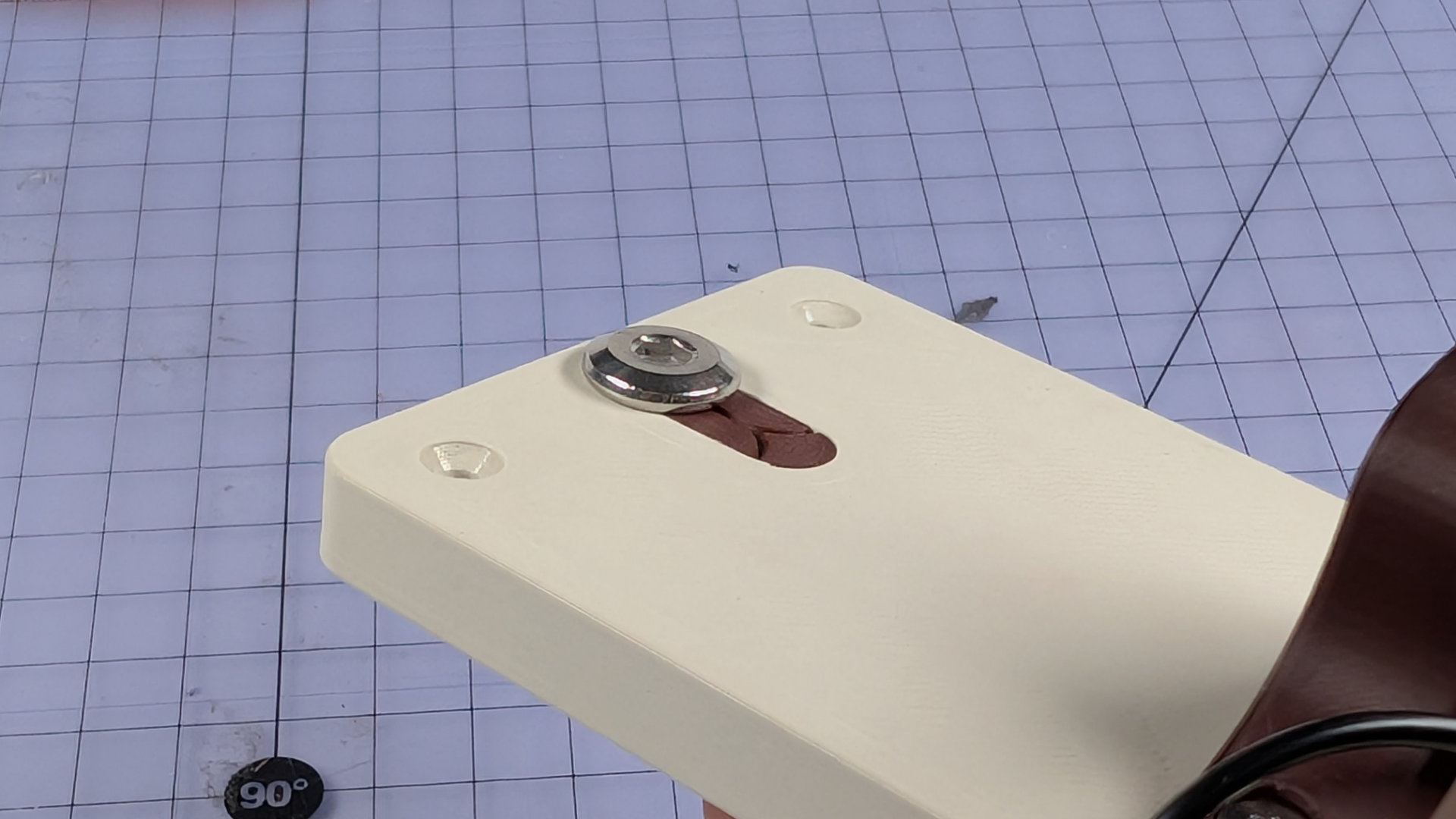
The front contact is an M6x12mm flat headed bolt. It's secured inside a small, removable chip that nestles in the baseplate. There are two chip designs; one that positions the contact centrally, and one that places it at the end of the slot. The latter can be flipped to place it forwards or backwards of centre. These three positions seem to suit most teaspoons.
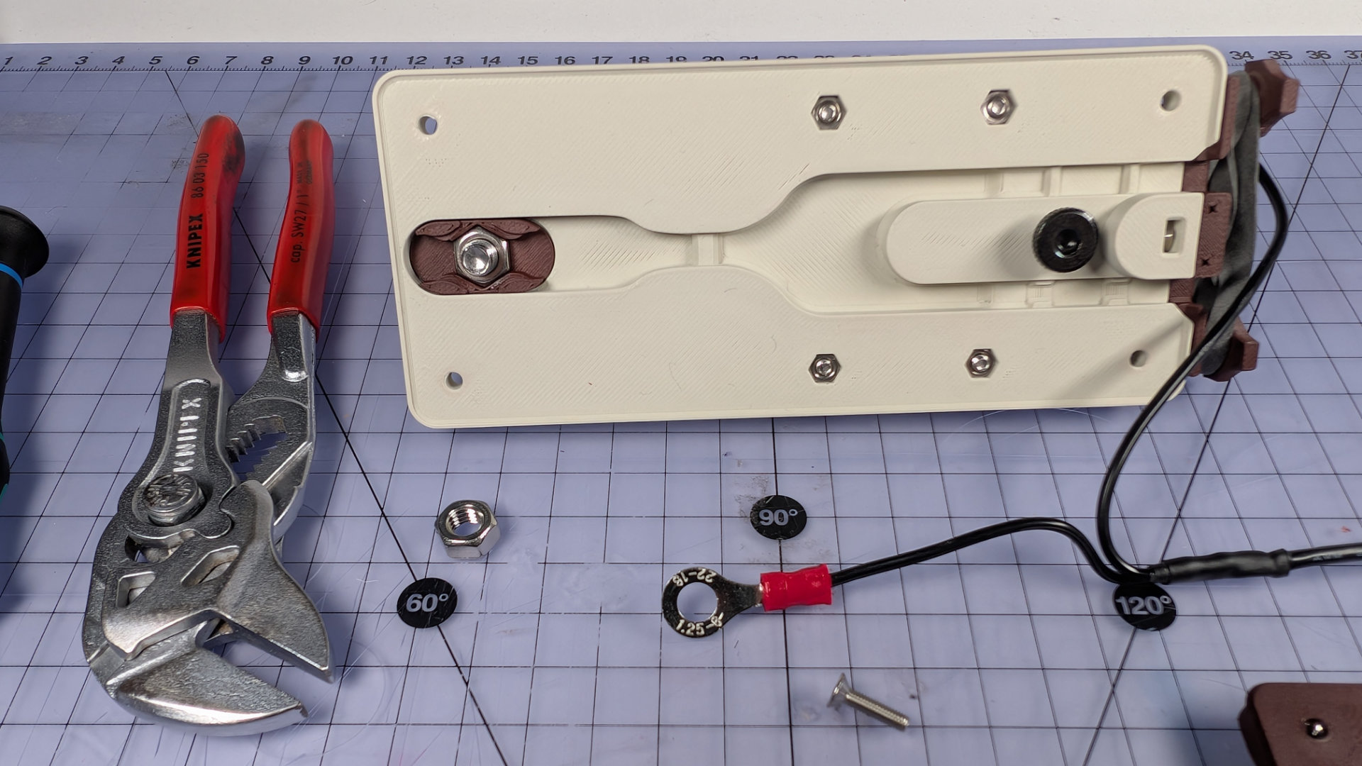
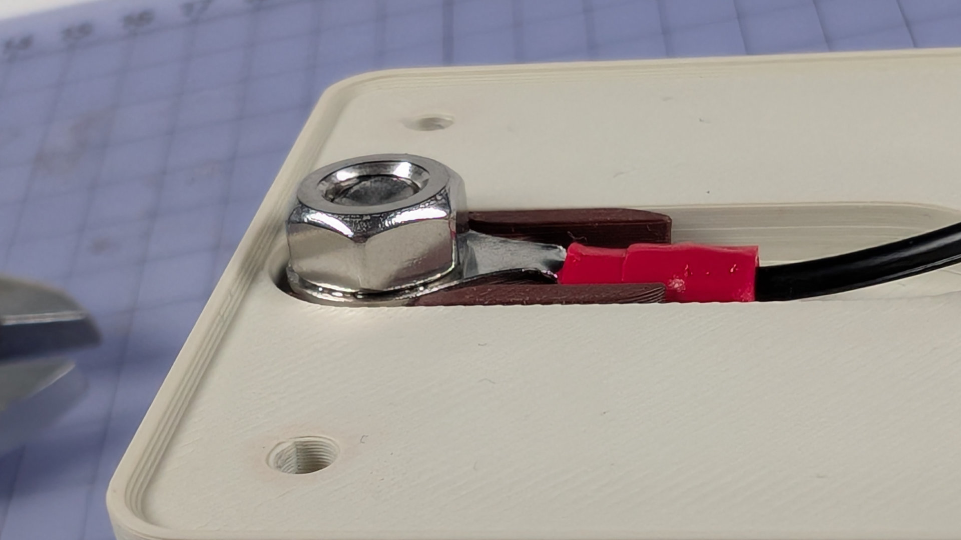
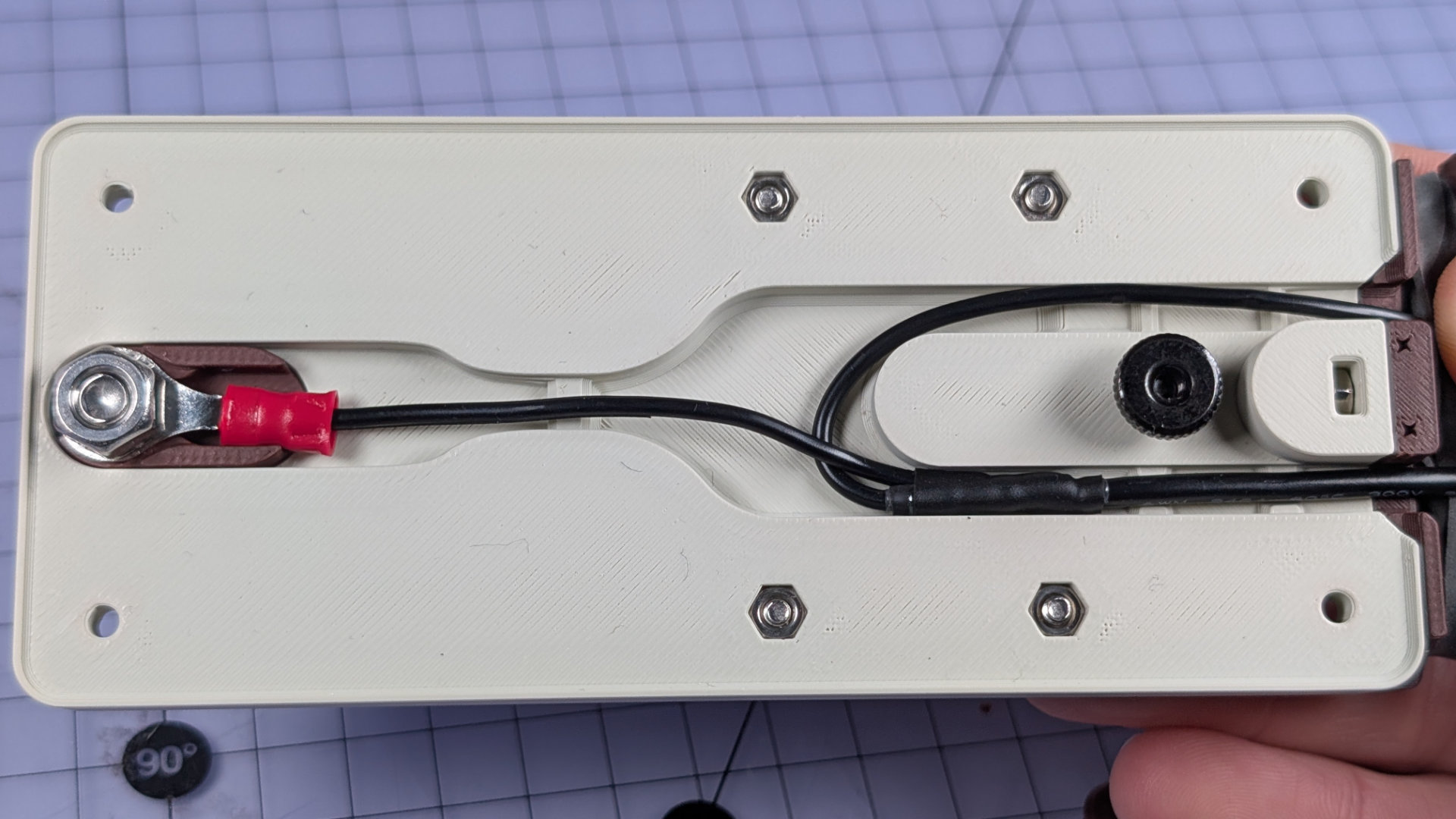
Underneath, inside the key, two M6 nuts sandwich a ring crimp for the wiring.
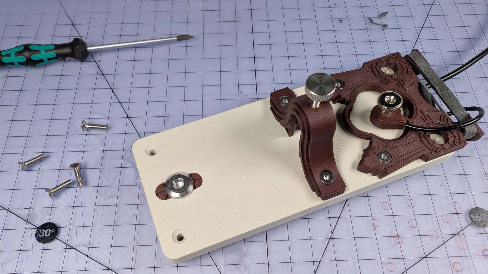
To reconfigure your front contact, first remove the spoon (see "Spoon Removal" above), then park the magnetic contact on top of the baseplate. Next, remove the four M3 screws at the corners of the baseplate. This will release the bottom cover. Flip the key over.
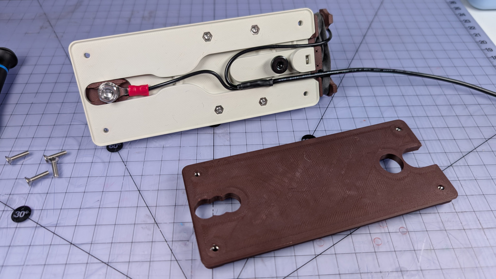
Now, using a 10mm wrench, remove the first M6 hex nut and lift the crimp off the front contact bolt. At this point, the wiring might fall out. If you want it to stay in place, a piece of scotch tape can retain it.
Next, flip the key right side up and use a 4mm hex key to remove the front contact bolt. The flip chip should then drop or easily push out of the baseplate. The M6 nut inside the flip chip is a half-nut (lower height than a standard one), and a push fit. If you're changing chips and the nut is lodged in the old one, you can use the M6 bolt as a tool to push or pull it out.
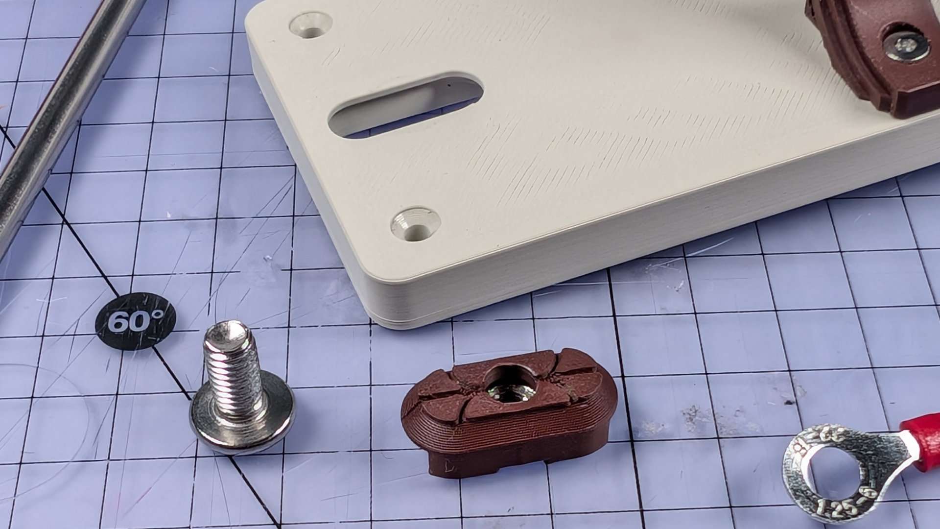
Place the half-nut in the new chip, and push the chip into the baseplate socket.
Insert the contact bolt from above, and tighten it down until the flip chip doesn't move or rattle. Make sure of this, because if the nut, chip and baseplate are a tight fit for each other, there might be a sneaky gap between the nut and the inside of the chip.
On the underside, place the crimp terminal over the contact bolt. Make sure to observe the right orientation. It should sit as far down inside the central channel as it can, rather than above it.
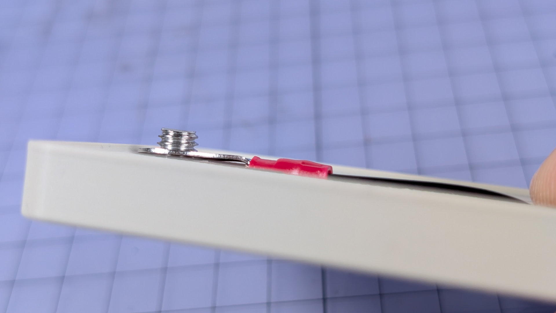
Now add the second M6 nut, and tighten it down. Once that's tight, the ring crimp should sit flush inside the flip chip.
Reinsert the wiring, making sure the heatshrink is within the deeper central recess of the baseplate. The magnetic contact wire should be in the channel with the taller strain relief walls , and the mono-socket wire should be in the channel that has those walls notched. Again, tape may be your friend here when trying to keep all the wires in place.
Replace the bottom cover, and you're done.
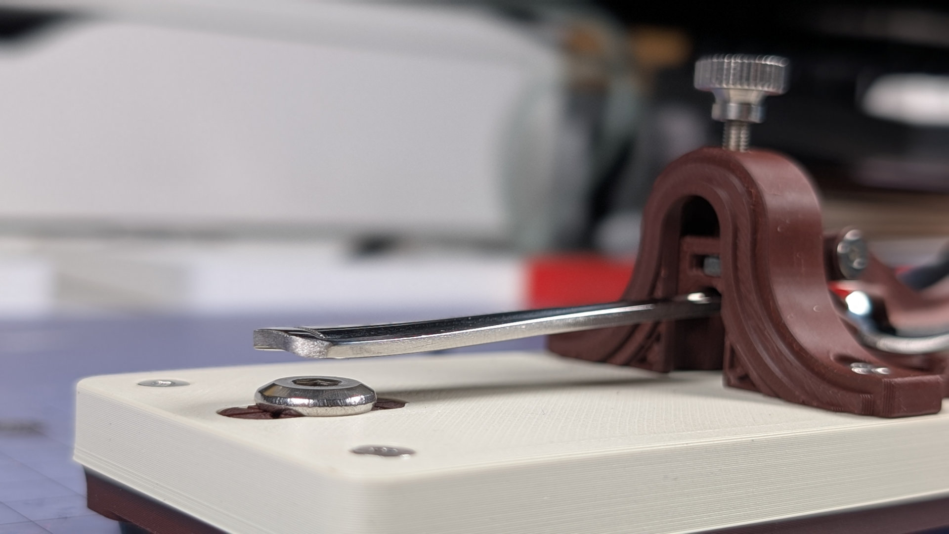
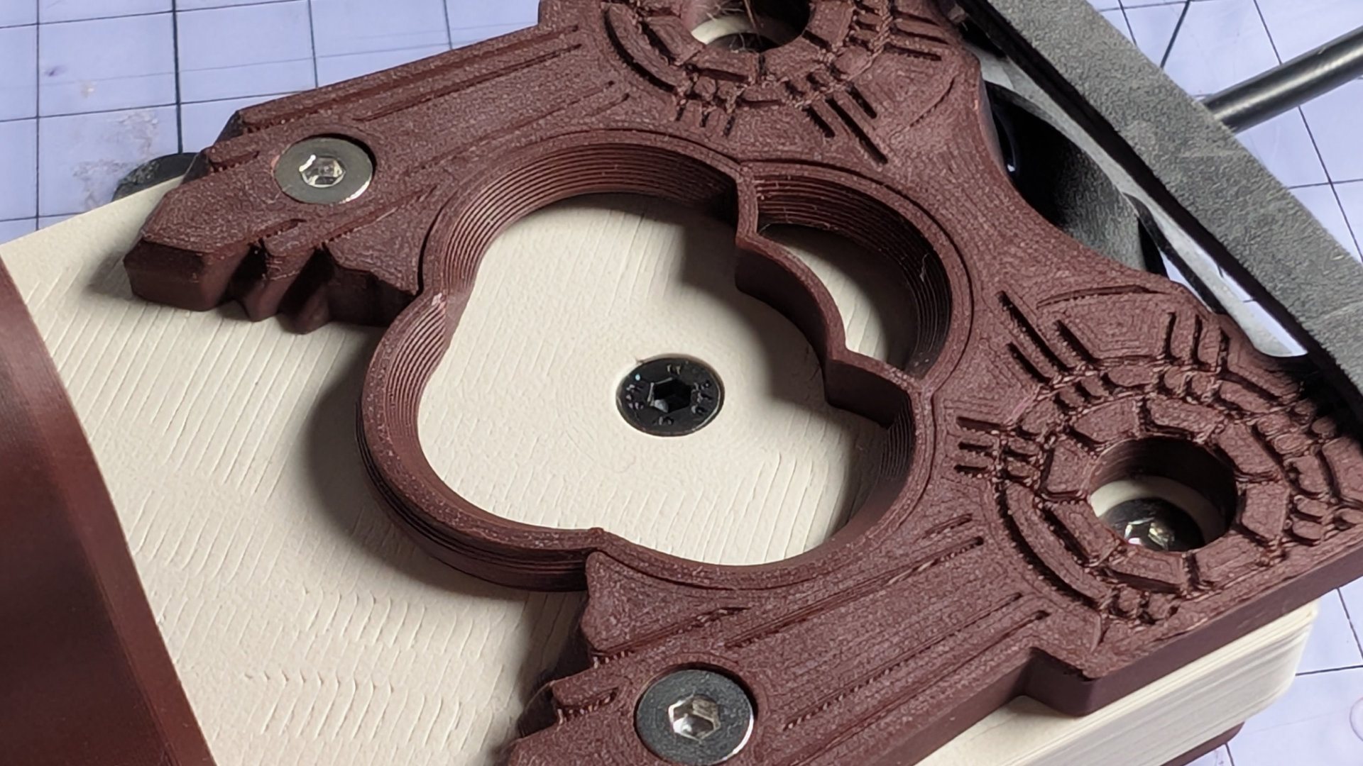
Bearing Inserts
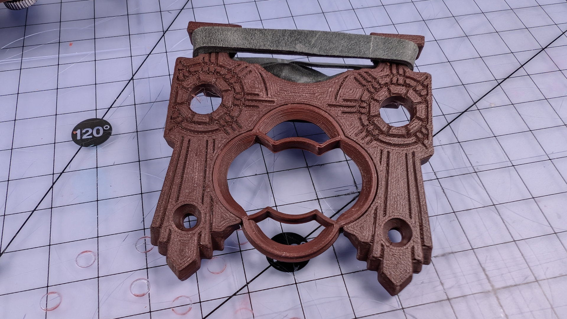
The bearing insert is a consumable part that the spoon slides on. It's designed to be a small and quick 3D print, to reduce plastic waste.
There are three types of bearing insert. Most spoons seem to work best with this type, configured with the two contact points (the pointy bits closest to the centre of the insert) toward the back.
The other two insert types have either four contact points, or none, and may suit differently shaped or sized spoon heads. When the contact points wear, the insert can be flipped over before needing replacement.
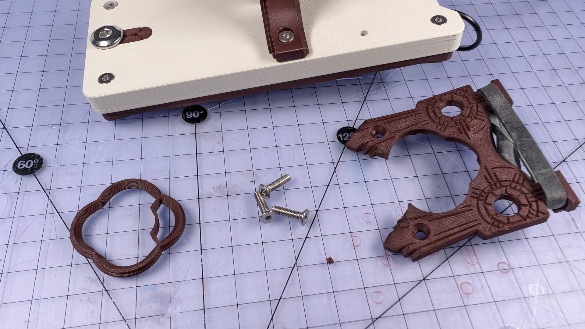
To replace an insert, first remove the spoon and park the magnetic contact on the underside of the key. Next, remove the M3x12mm screw in the back of the key, underneath the elastic band.
Then remove the two screws at the front of the spoon plate. It should now lift off the baseplate.
Remove the insert, and place the new one in the spoon plate socket.
Reinstall the front two screws but don't tighten them fully. Next, insert the rear screw and tighten it fully. The hole depth inside the baseplate is dimensioned to prevent over-tightening. Finally, tighten the front two screws of the spoon plate.
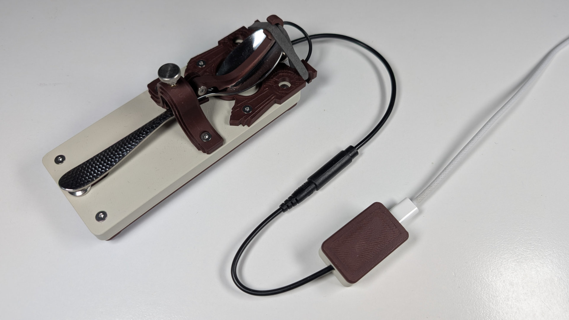
Connectivity
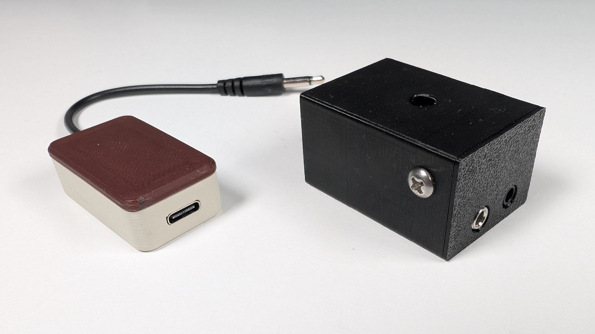
The default Teaspoon Telegraph build connects via a 3.5mm monojack socket. With a patch lead, you could connect it to a VAIL Adapter, which is perfect for people wanting to get deeper into amateur radio and CW. You can buy a kit, or buy a completely assembled one from them at the link. Their documentation also includes a section on setting up VAIL to work with MORSE.
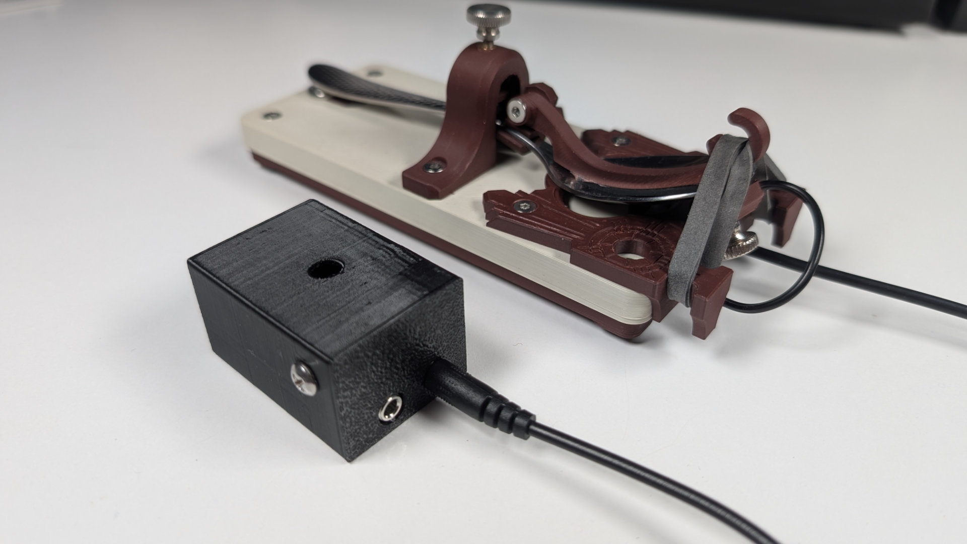
For people who just want to play or exhibit videogames, but maybe not get into amateur radio, I designed QMKeybox (all source files for it, including the firmware, are also on GitHub). It's a VIA-compatible, single-button, USB-C keyboard with a monojack out. It defaults to acting as a space bar, but can easily be remapped to any other key or even a macro.
If you don't mind a bit of DIY jank, you could solder connections to the circuit board of an old mouse, as explained in this video.
There are many other ways to connect a Morse key to a computer, some detailed in this Steam forum thread. Having to build the QMKeybox notwithstanding, it and the VAIL adapter seem to be two of the simplest and neatest.
From here, you can go back to the teaspoontx overview, or read the Teaspoon Telegraph Print Guide.