Teaspoon Telegraph Print Guide
Up: teaspoontx
Introduction
Printing parts for the Teaspoon Telegraph should be quite straightforward, but with the larger parts, there are a few critical things to make sure of, and some refinements possible in the way they're printed.
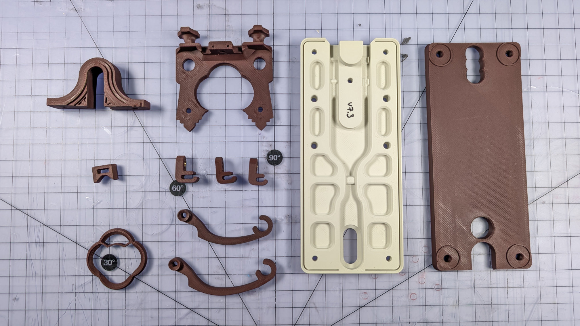
Those parts are the travel adjuster, the spoon plate, the baseplate, and the bottom cover. Additionally, your slicer might compromise the magnetic contact housing. All of these parts and correct print orientations are shown below.
Other Parts, Filament
All the other parts should be straightforward to print, with obvious best orientations. They all have at least one completely flat face designed to be placed on the print bed.
All examples shown were printed on a Bambu A1 using a Biqu Glacier build plate, pre-lockdown firmware, and Orca Slicer. The two filaments I used are:
- eSun Matte Light Khaki PLA.
- ERYONE Matte Ruby Red PLA.
Baseplate
Print the baseplate upside down and by itself, like this:
Printing it centrally evens out any irregular heating and, if it does warp slightly, will at least tend to make that symmetric. Off-centre printing, e.g. when trying to print multiple baseplates at once, can result in a Morse key that rocks like an annoying cafe table.
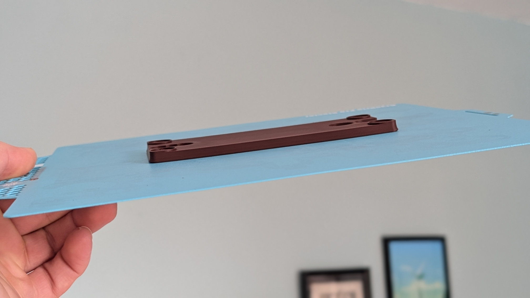
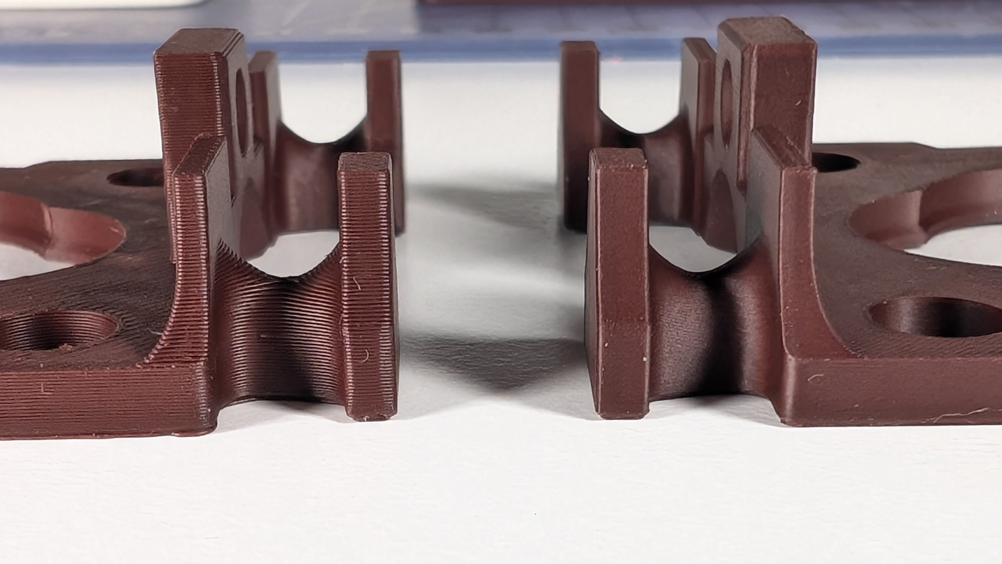
Leave the build plate on the bed to cool down before removing the part. I've designed some anti-warping features into the baseplate, but still find the corners can be a problem. Here's a comparison of an earlier version (right) and later one (left):
Corner lift can mess up the final layers, compressing them and creating horizontal banding. You might need a brim or mouse ears, but I prefer to print without if I can, especially on this high grip plate.
A more organic infill pattern, such as Gyroid or TPMS-FK, might also help you reduce warp.
Bottom Cover
Like the baseplate, the bottom cover is printed upside down. Unlike the baseplate though, this time we're going to exploit warping to get a better bottom. In seconds! Again, print by itself in the centre of the bed, but take the build plate off as soon as it's done printing.
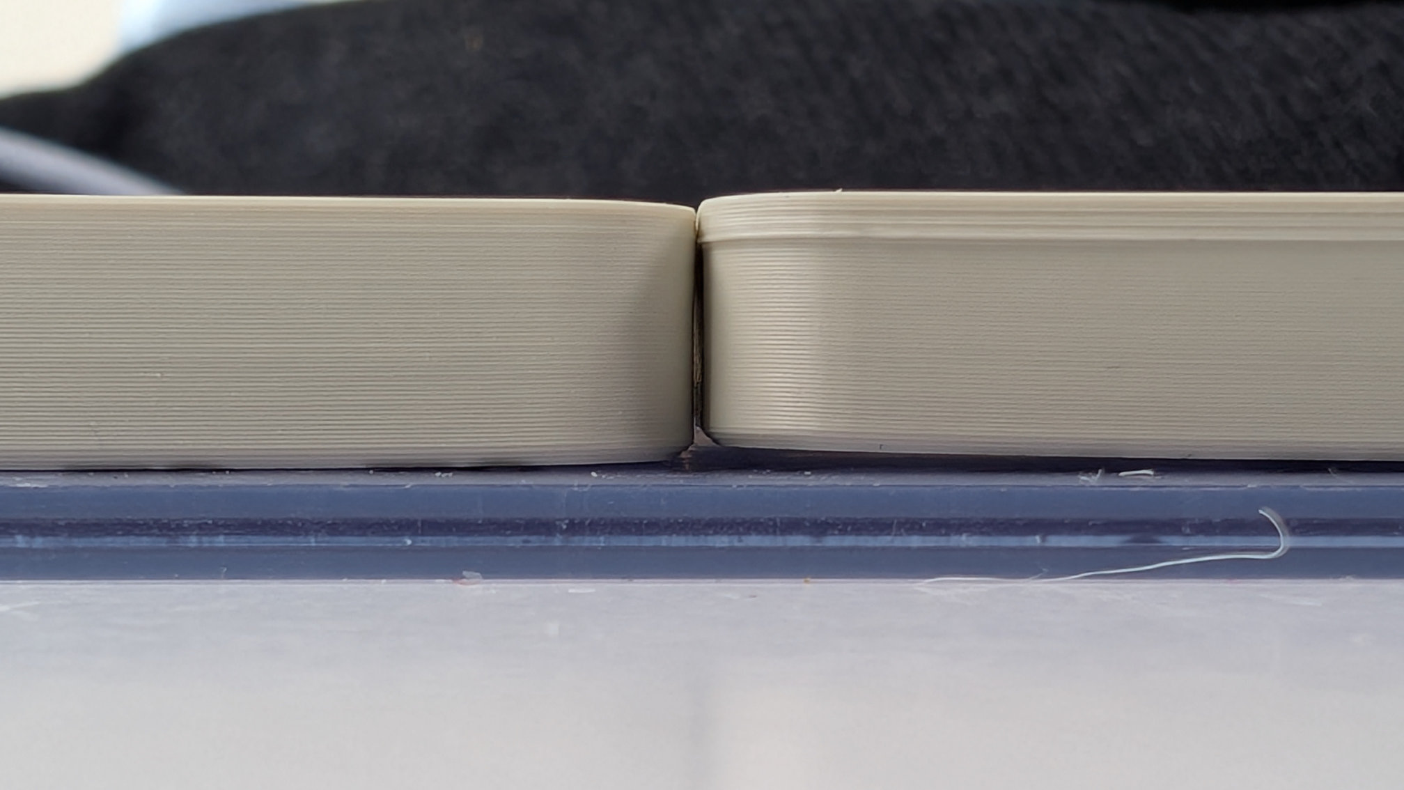
This will cause the corners to warp upward as it cools, resulting in gaps like this:
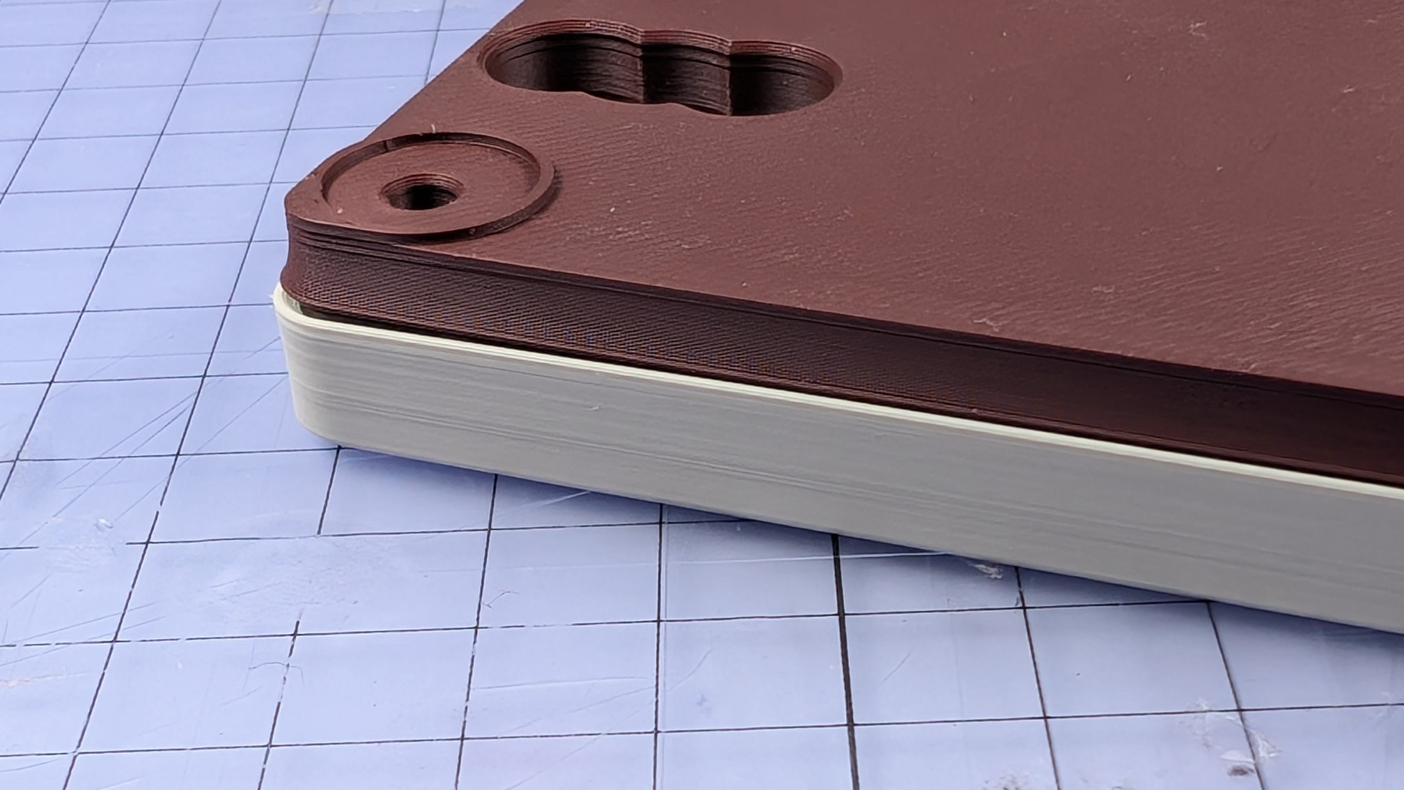
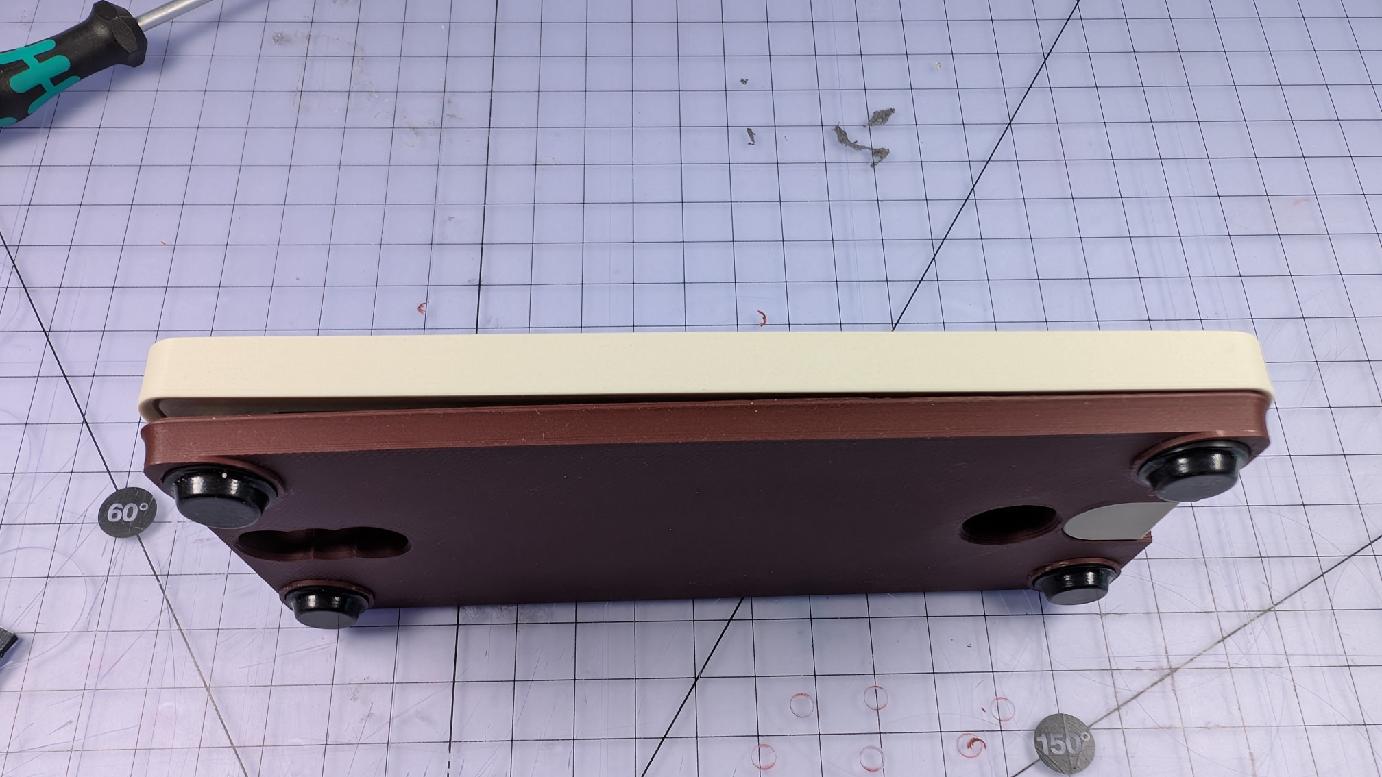
That's a good thing. During assembly, this warping will ensure the bottom cover fits tightly against the baseplate, with its centre sprung upward, and its ends pulling down on the corner bolts. Shown below is an assembled bottom cover with bolts holding it tight to the baseplate on the right, creating a gap of 3 - 4mm to the left. Because of that curvature, the remaining corner fixings will close it up against the baseplate along its whole length, with no gaps.
Travel Adjuster
The travel adjuster should print without supports, but they won't harm it. With or without support, in the slicer you should place it on its back face, like this:
While that does ease printing of the decorative front face, the main reason for this orientation is mechanical, not aesthetic.
It's critical that the layer lines of the travel adjuster body and slider run with this orientation. That way, the lines slide along each other like rails, instead of grinding over each other like opposing sets of teeth.
A high grip, low texture build plate gives a nice finish on the back face. This way of printing does create a weak point at the mounting holes either side though, so during assembly, do make sure not to over-tighten the fixings on this part.
Magnetic Contact Housing
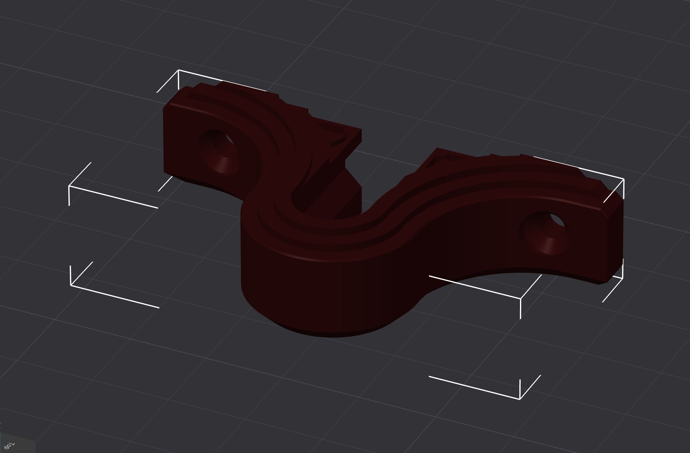
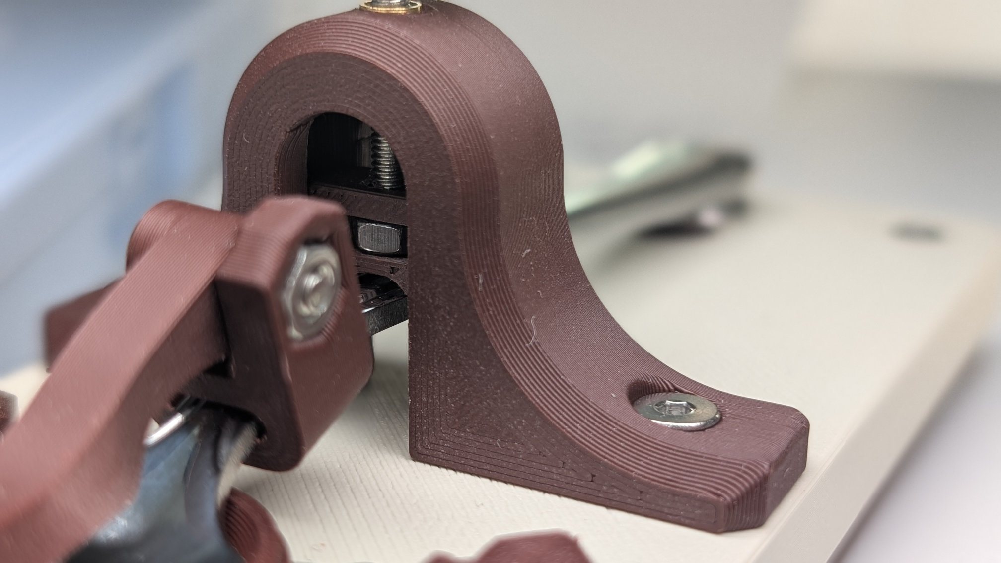
Your slicer might suggest printing like this, which you shouldn't:
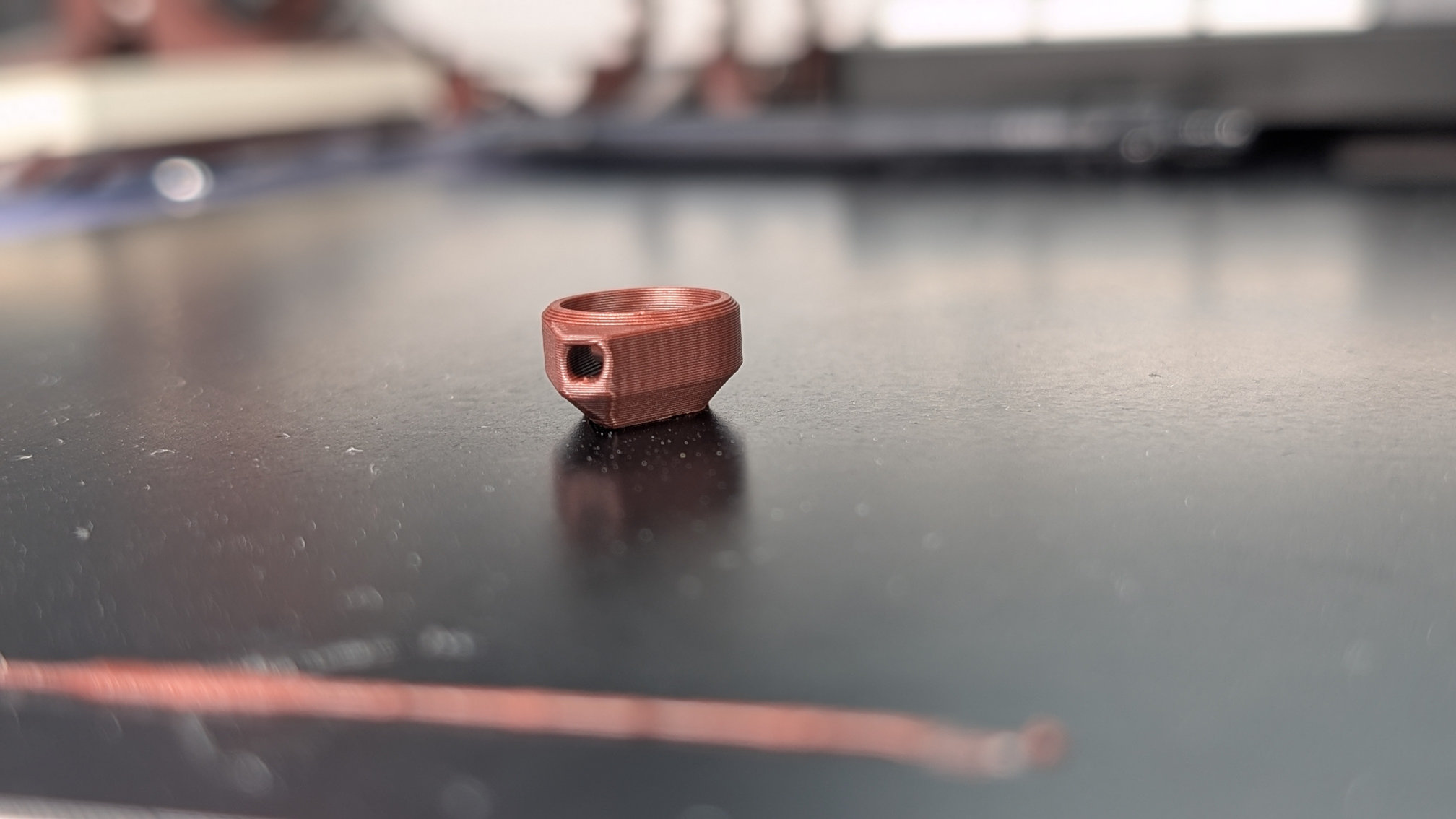
Print it like this instead, with or without supports:
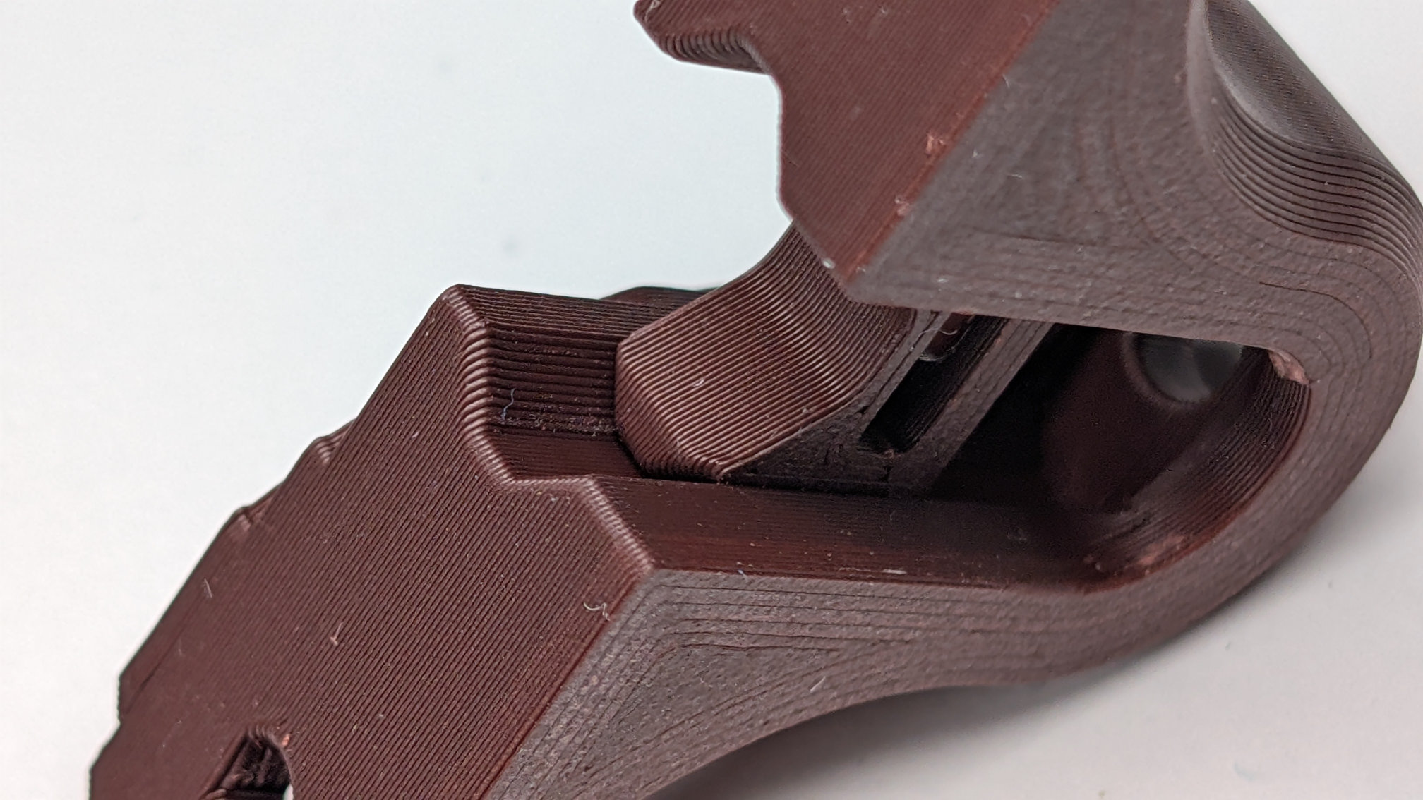
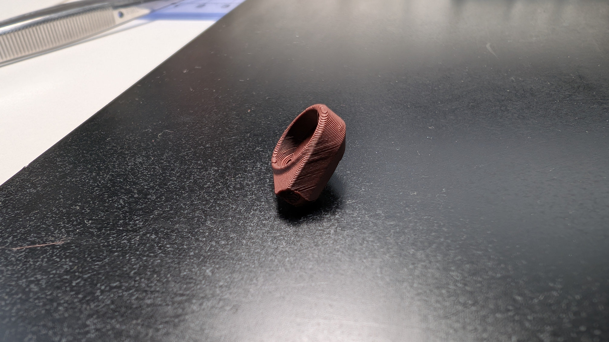
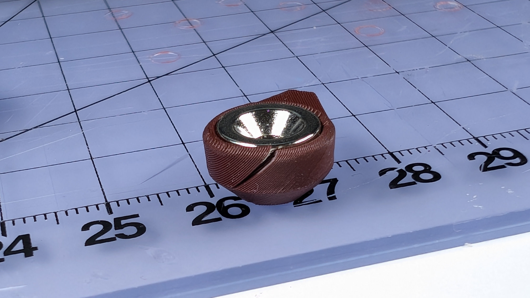
This part is a push-fit for a 10mm countersunk magnet, so needs radial strength. Printing diagonally reduces that, meaning it can pop like this during assembly:
Spoon Plate
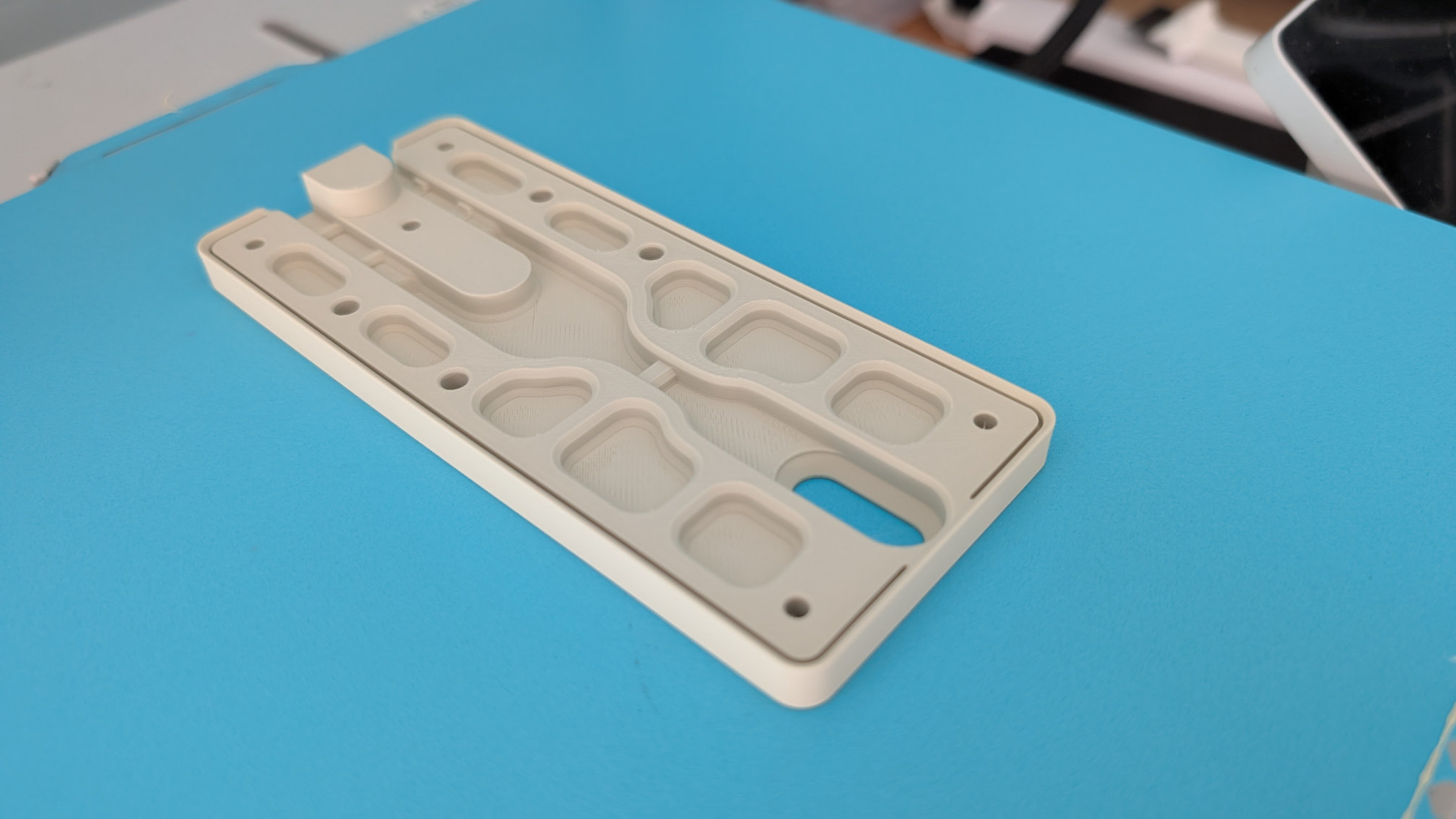
Like the baseplate and bottom cover, the spoon plate should be printed upside down:
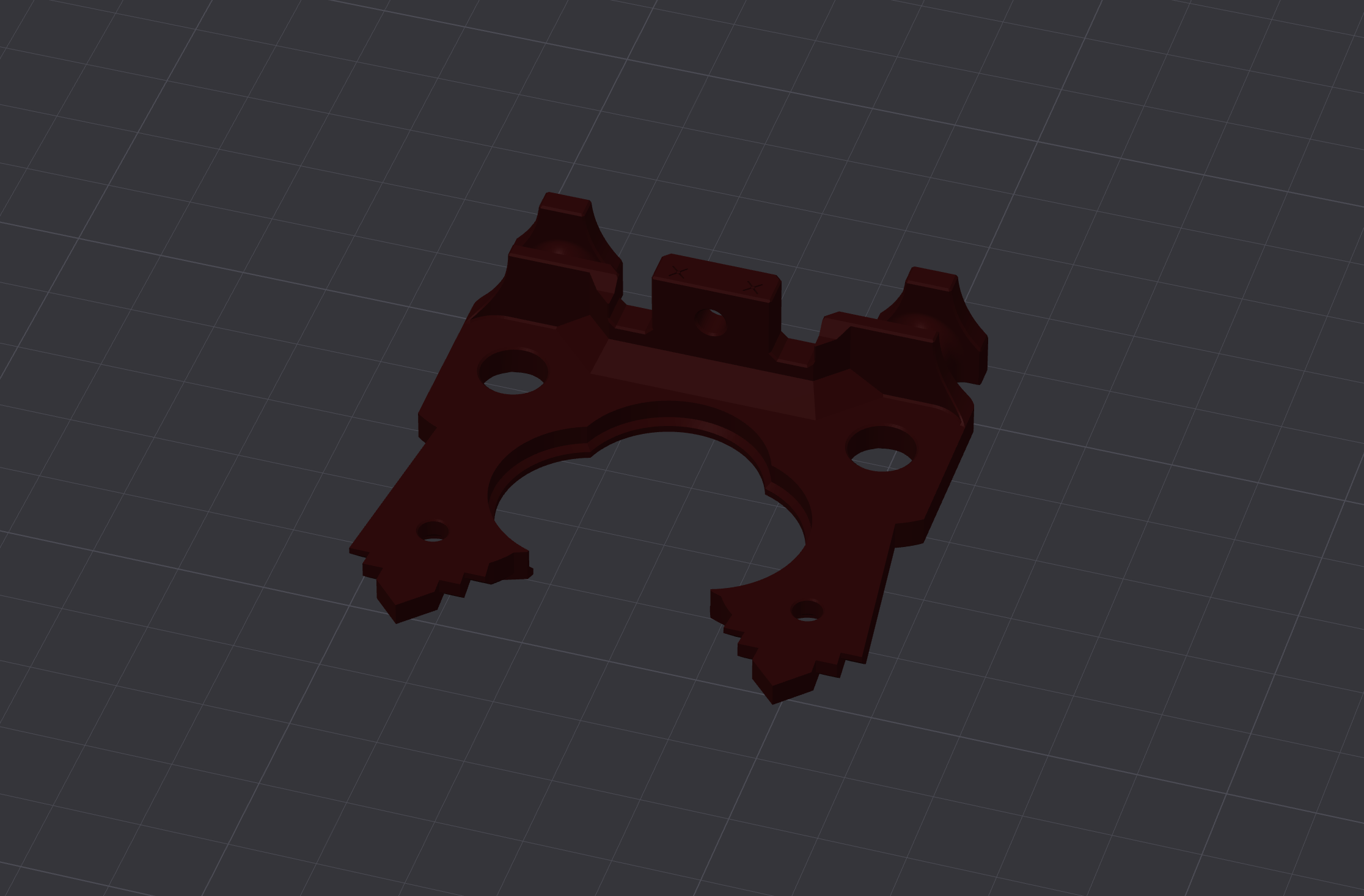
Of all the parts of the Teaspoon Telegraph, this one takes the most force in use, so should be printed for strength.
Fusion strongly disliked the surface detail I put into this part, so much so it took two attempts to model. My first method caused it to use all available RAM, then write a fifty gigabyte page file before I realised what was going on and force-closed it. No idea why, because the exported .stl was only 700Kb. Second attempt was a bit less intense, but still chuggy. As well as the final art deco version, I've provided a .STEP file for a simplified one, with a plain top surface in case you want to modify it into your own design.
For the decorative version, I find a 0.4mm nozzle can give passable results as long as I don't look too closely. A 0.2mm nozzle can manage ridiculous amounts of detail, but:
- A textured PEI plate will eradicate fine surface details.
- Nothing I tried got the first layer to stick on a smooth PEI plate.
- Bambu's Supertack and Biqu's Glacier plates both held onto the first layer a bit too well, resulting in surface damage like this:
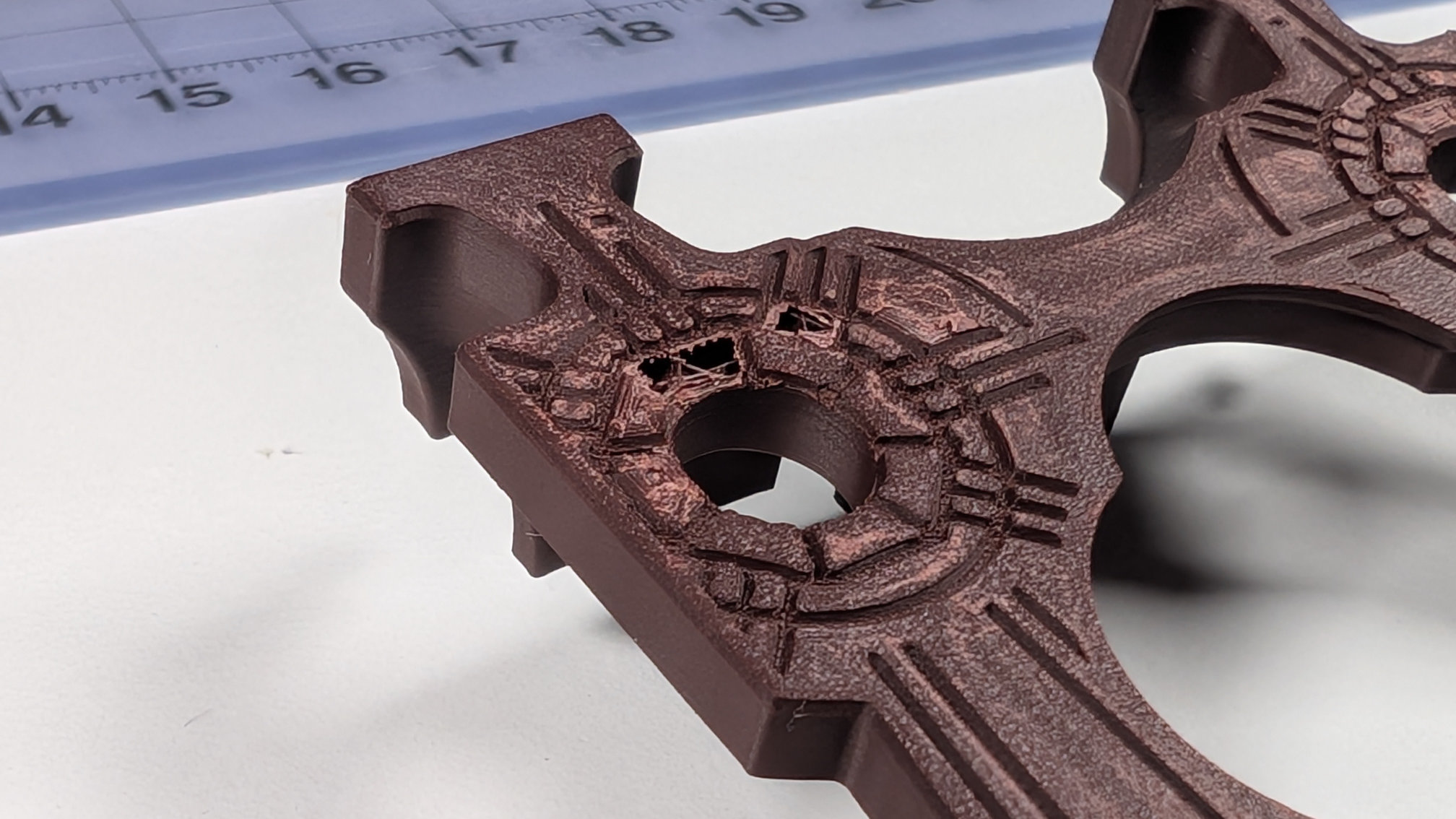
By greatly increasing the shell thickness, I found parts printed with 0.04mm detail layers avoided having holes ripped into them like above, and were strong enough for use, but they still picked up some surface marring from any build plates sticky enough to hold onto them.
Whatever nozzle and plate you use, variable layer heights are very much your friend here.
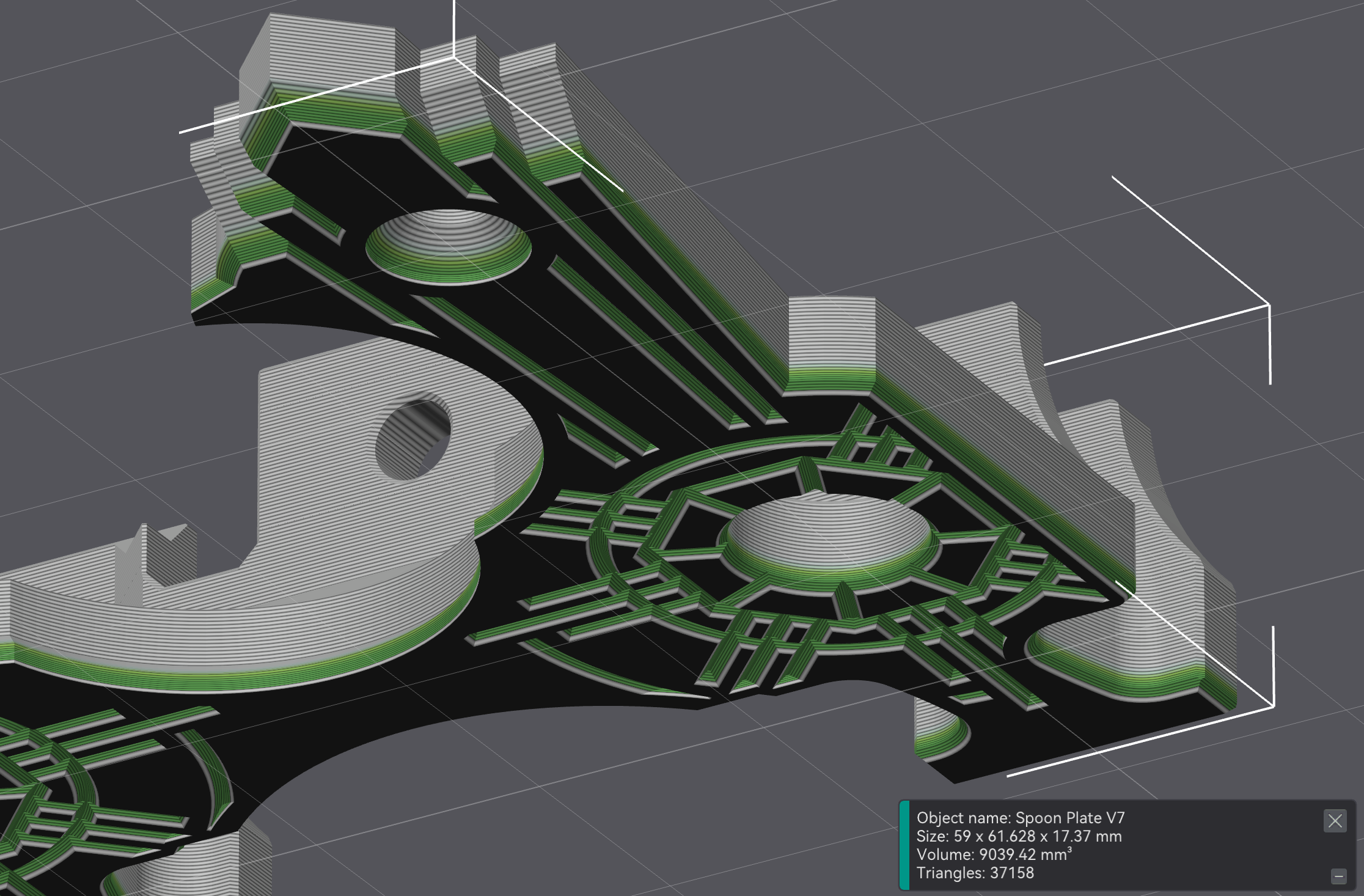
Variable layer heights with a 0.4mm nozzle can give a mechanically strong print with acceptable surface detail in about 30 - 45 minutes. On my printer, a 0.2mm nozzle can take details all the way down to a 0.04mm layer height, which is incredible, but even applying that to just the first millimetre or so of the print quadruples the print time for me.
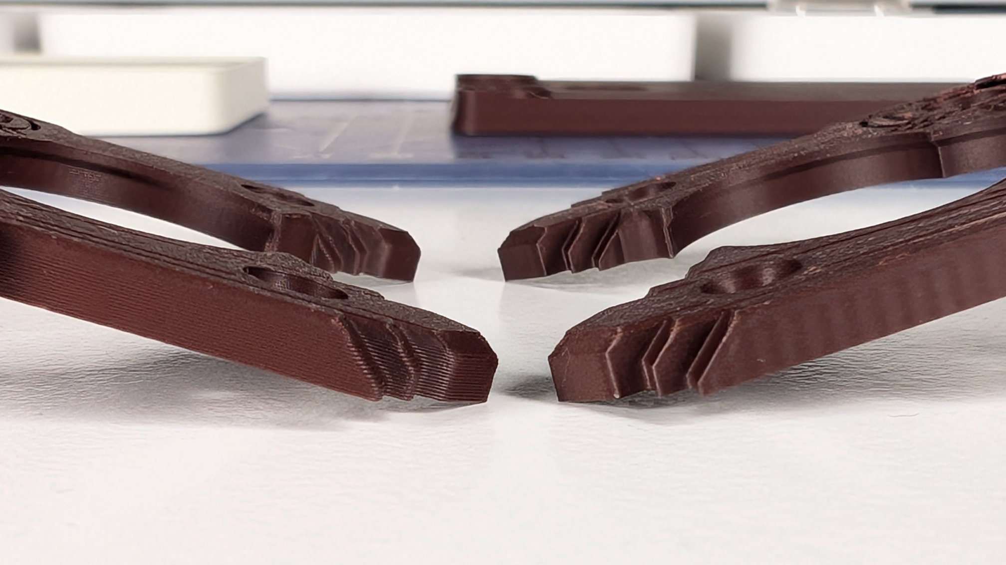
Here are some close up comparisons of variable layers with a 0.4mm vs. a 0.2mm nozzle. If using very small layer heights and a 0.2mm nozzle for detail, make sure to double your wall loops, bottom-shell and top-shell layers in order to put strength back in. If you don't, you'll end up with a part that easily bends and splits at layer lines. The damaged one a few images back was like this, and felt almost like it was made of parchment.
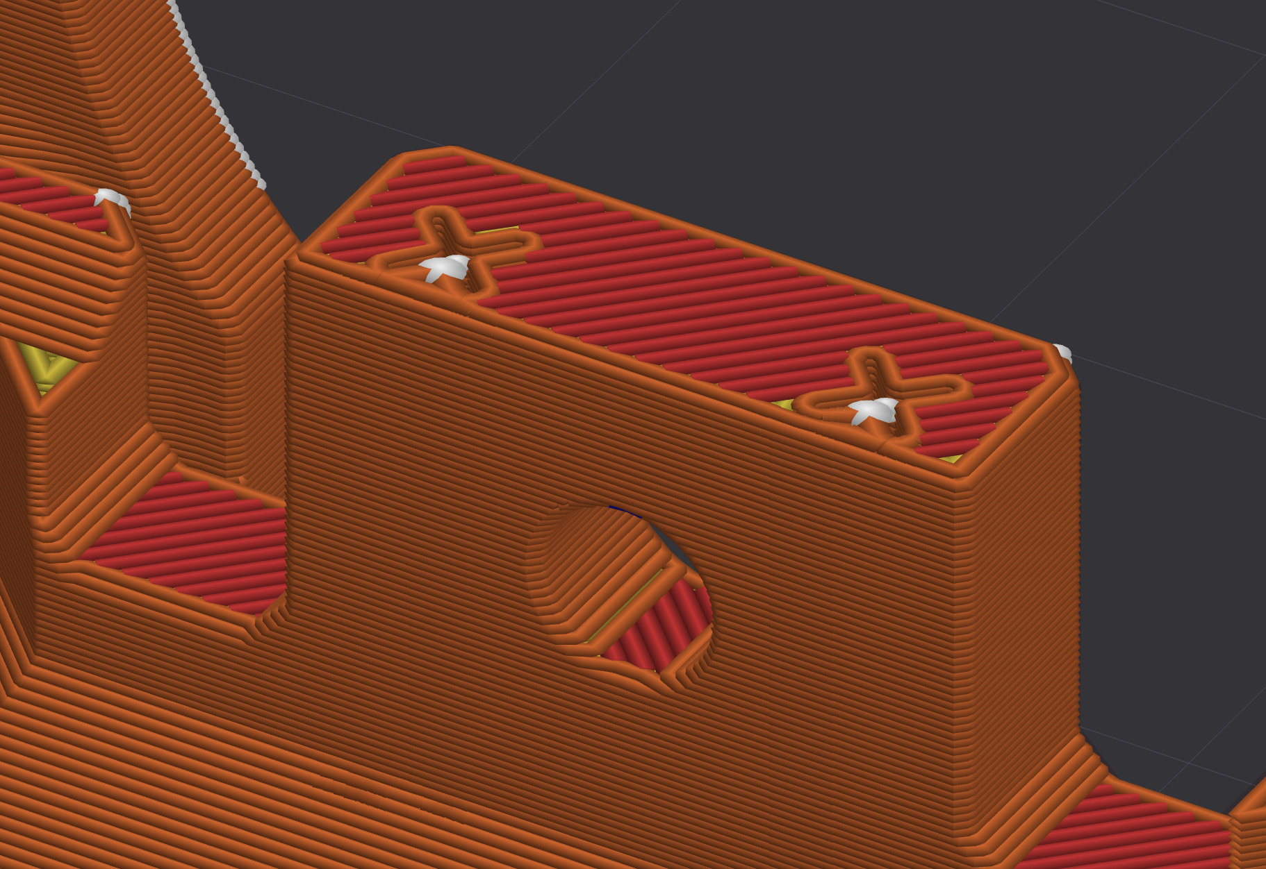
As with most of the parts for the Teaspoon Telegraph, the spoon plate should print fine without support. The rearmost hole, shown below, may sag a bit but I typically find that's not enough to hamper assembly:
Like the mounting holes for the travel adjuster, the orientation of this hole ideally wouldn't cross the layer lines like this, because over-tightening a countersunk bolt could break them apart. While not ideal, this configuration was the best way I found to fix the spoon plate to the baseplate, while also creating clearance for the wiring and magnetic contact.
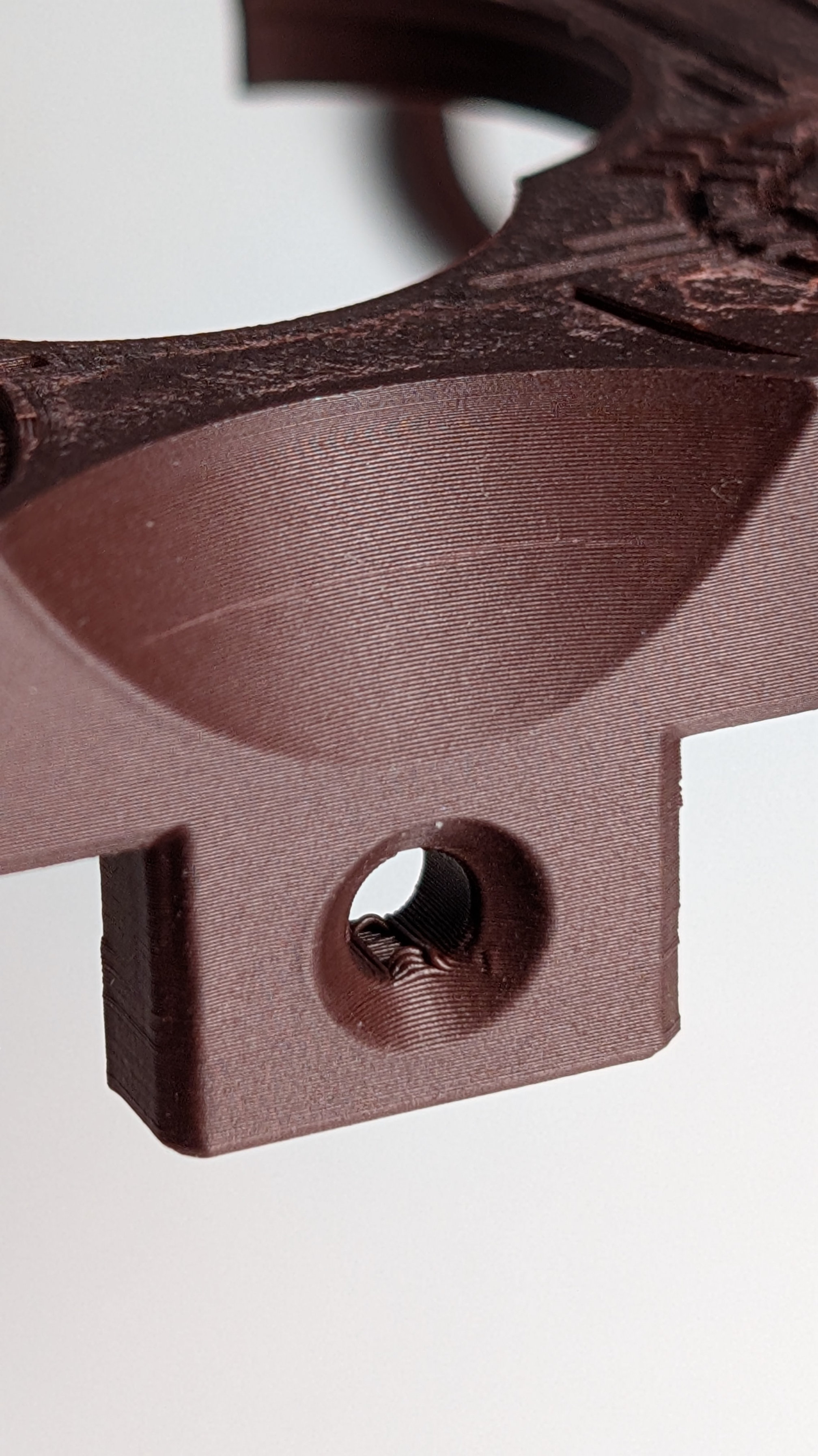
There are two features to prevent breakage. The first: micro-features either side of the hole, to make sure there's more material around this area rather than just infill:
The second is that the depth of the corresponding hole in the baseplate is set to bottom out a countersunk M3x12mm machine screw just before it can start crushing the spoon plate. So long as you use the right fixings and don't assemble things in the style of a gorilla, it should be difficult to break.
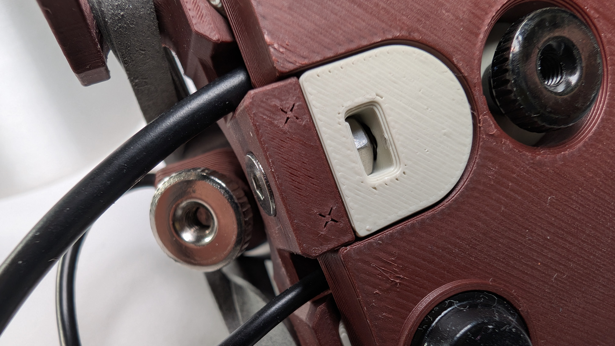
Below you can see the micro-features in the spoon plate, and that a fully tightened screw head sits just a little bit proud of it. A deeper hole (or shorter fixing) would let the tapered screwhead advance until it split layers apart.
Still To Come
This is a first draft of the print guide. Later, there will be links to some other docs plus .STEP, .stl and .3mf files.
From here, you can go back to the teaspoontx overview, or read the Teaspoon Telegraph Manual.