Teaspoon Telegraph Build Guide
Introduction
If you're printing the parts yourself, first see the Teaspoon Telegraph Print Guide.
Some of the parts shown here might differ slightly between steps, as I photographed most steps using version 6 of the Teaspoon Telegraph, then refined it into a version 7 before publication. I also found nicer hardware options for some parts. These differences all improve the final object in various ways, but don't change anything about the build.
Tools
Making and assembling a Teaspoon Telegraph requires the following tools:
- 3D printer
- 2mm hex key or driver
- 4mm hex key or driver
- 10mm spanner/wrench
- Soldering iron
- M3 heatset insert tip
- Wire strippers
- Wire crimping tool
- Silicone glue plus applicator tips
- Tweezers (optional)
- Scalpel (optional, useful for cleanup)
- Multimeter (optional, just for testing the very simple wiring)
Parts
You will need these 3D printed parts:
- Baseplate
- Bottom cover
- Spoon plate
- Bearing insert
- Travel adjuster
- Travel adjust slider
- Spoon hook
- Hook clip
- Magnetic contact housing
These components:
- A size 64 rubber band, or thereabouts
- Trailing 3.5mm mono socket
- 12.7mm (1/2 inch) round bumper feet
- 20AWG wire
- Heatshrink
- An M6 ring terminal, red crimp
- A 10x3mm round countersunk magnet
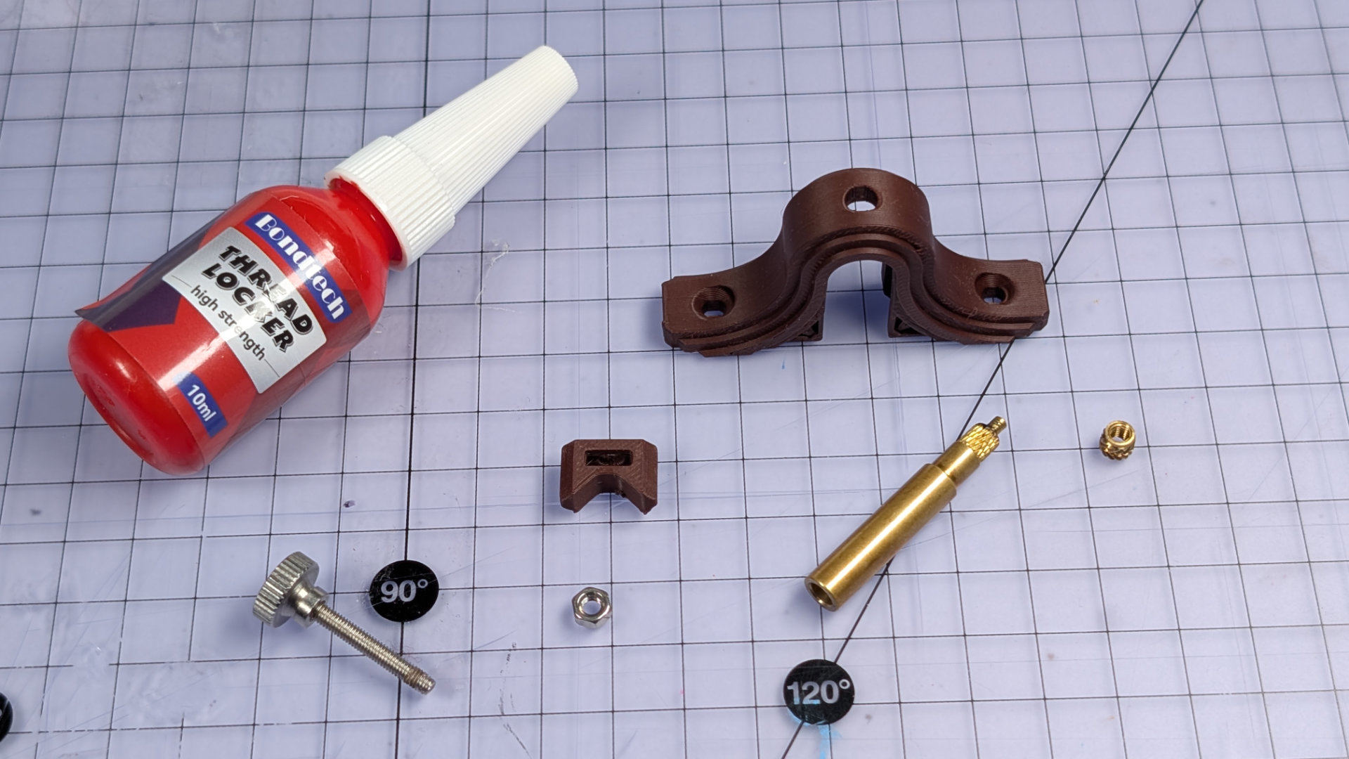
- Red threadlocker
- Adhesive backed rubber, 1 - 2mm thick (optional)
These fixings:
- One M6x12mm flat hex drive bolt
- Two M6 half-nuts (lower profile than standard hex nuts)
- M3x12mm countersunk machine screws (at least ten)
- M3 hex nuts
- M3 heat set brass inserts
- One M3x20mm thumbscrew (you can substitute any long enough M3 screw)
- M3 knurled thumbwheels (optional)
While there are some oddball fixings in that list, I've designed this thing to use M3x12mm countersunk machine screws at almost every fixing point. It's annoying when things use a different fixing for every hole, so I try to design things around one fixing.
The M3 thumbwheels are technically optional, but are a nice finishing touch. Combined with a long-ish M3 machine screw, they're also very useful for DIYing a useful nut-setting tool.
Finally you will need:
- A teaspoon, between 130mm and 150mm long.
If you intend to create parking spots for the magnetic contact, at least one of the M3 machine screws and one of the M3 thumbwheels should be a magnetic type of steel. You'll see later in this build that I used black oxide coated carbon steel for those two fixings, whereas the rest are stainless.
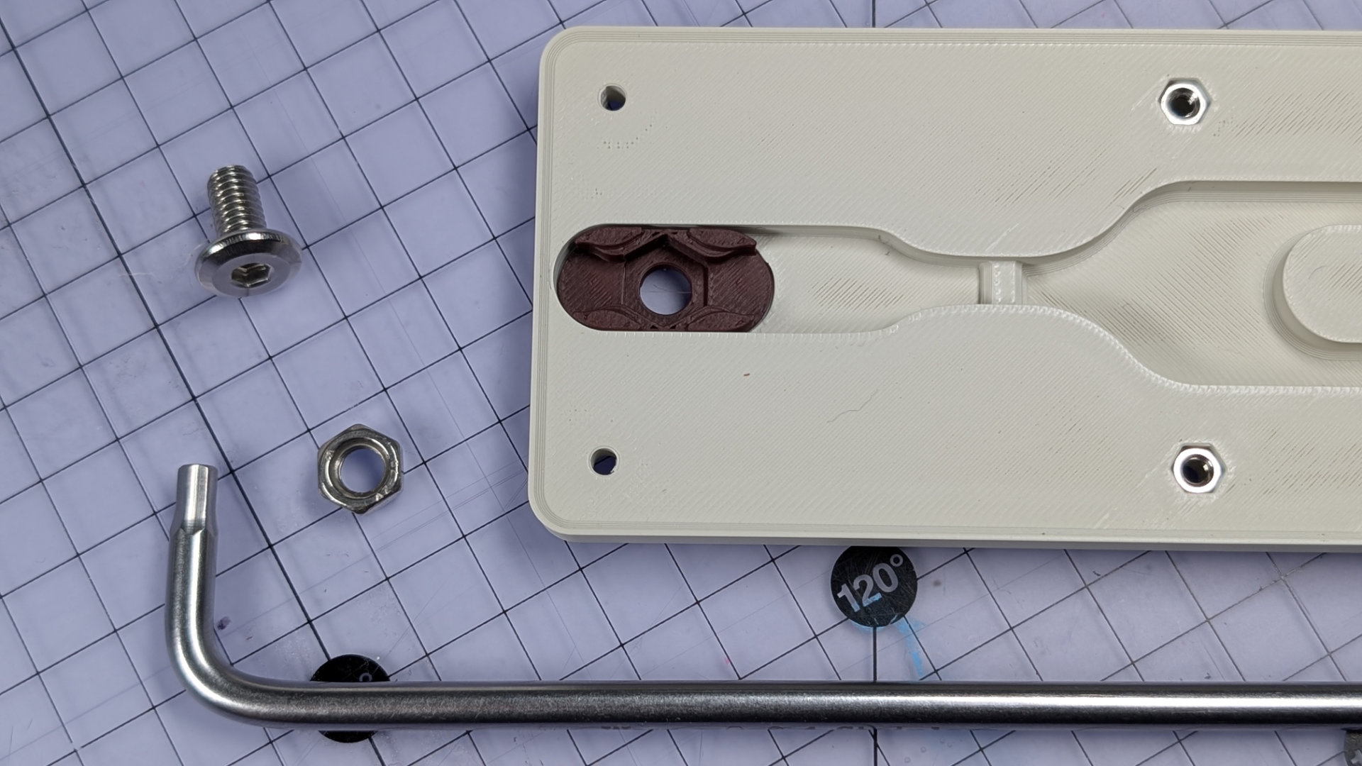
Nuts
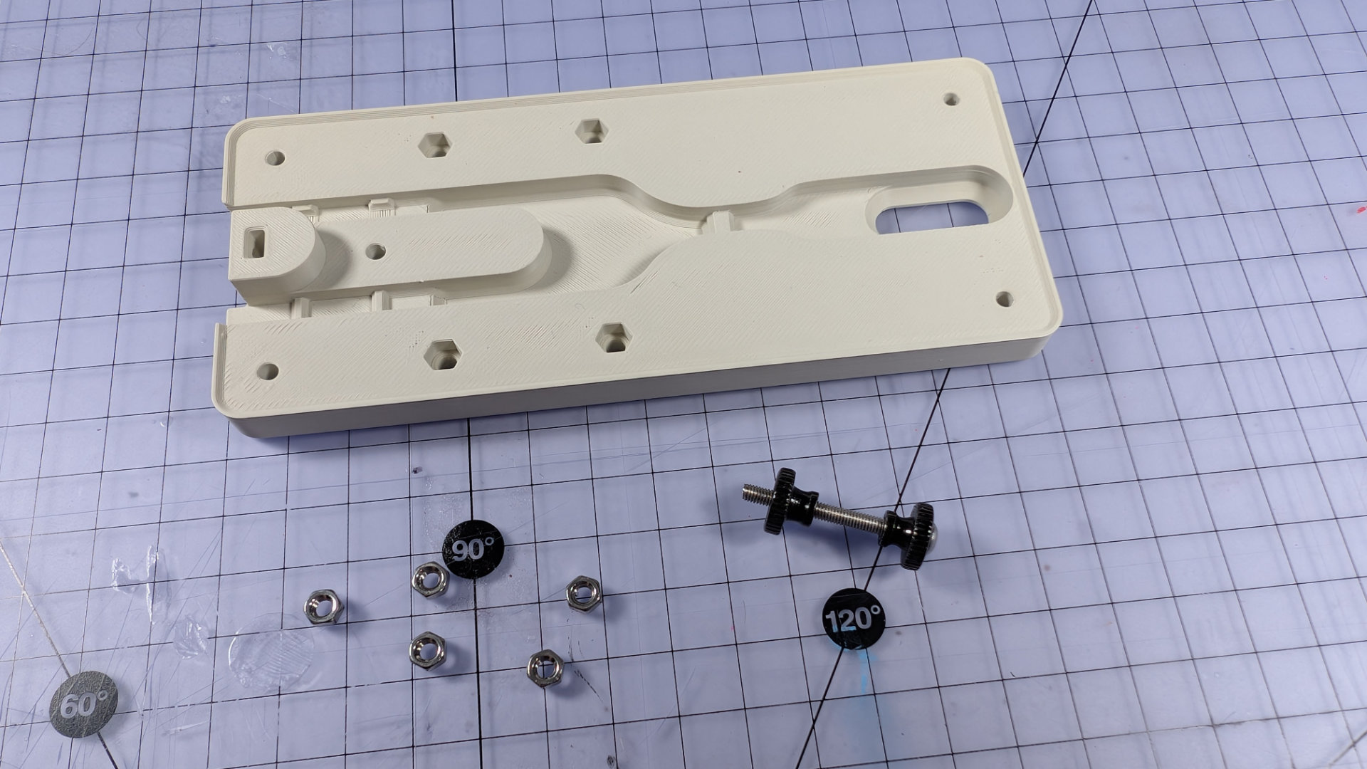
The first step is to insert M3 nuts into the bottom cover and baseplate. I did try versions of these parts with heatset inserts instead, but found hex nuts to be the preferable option in the baseplate and bottom cover. Brass inserts are unforgiving of even slight misalignment. Push-fitted nuts are willing to negotiate.
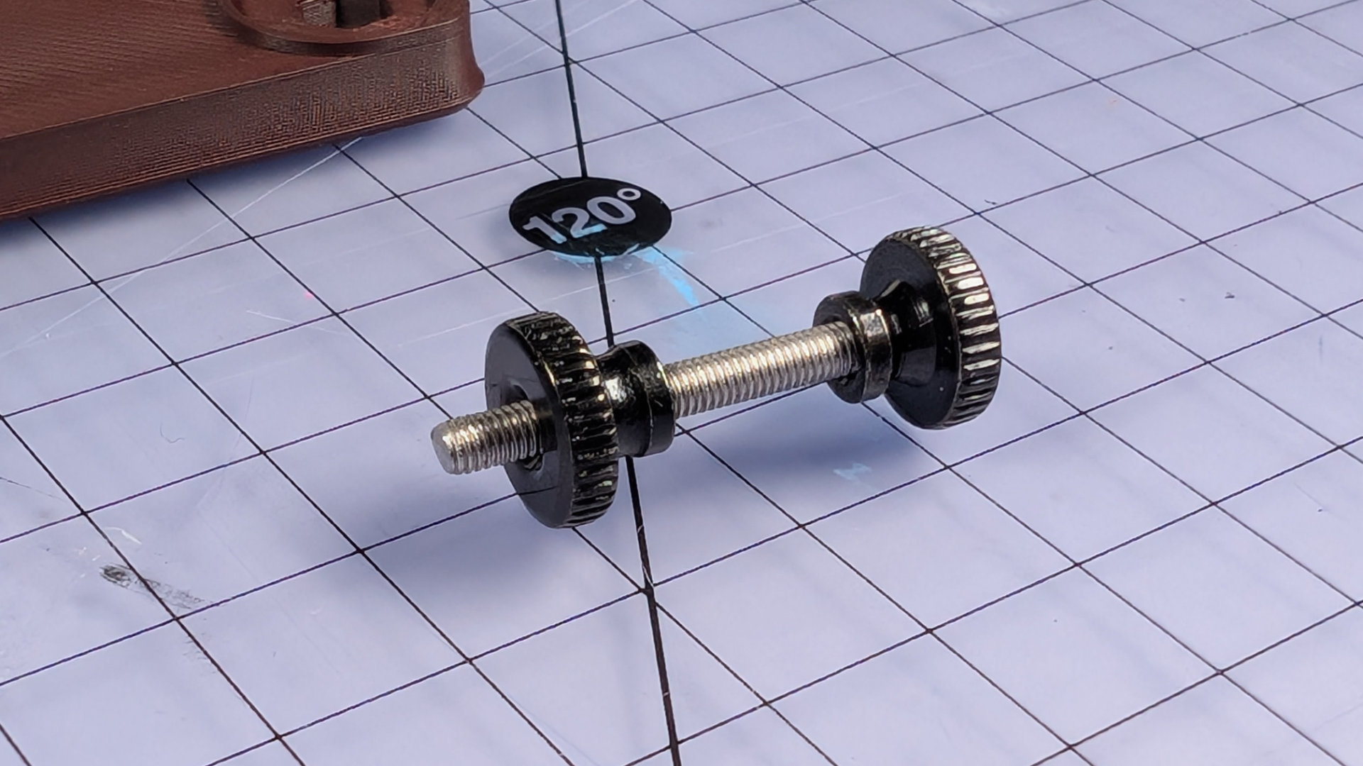
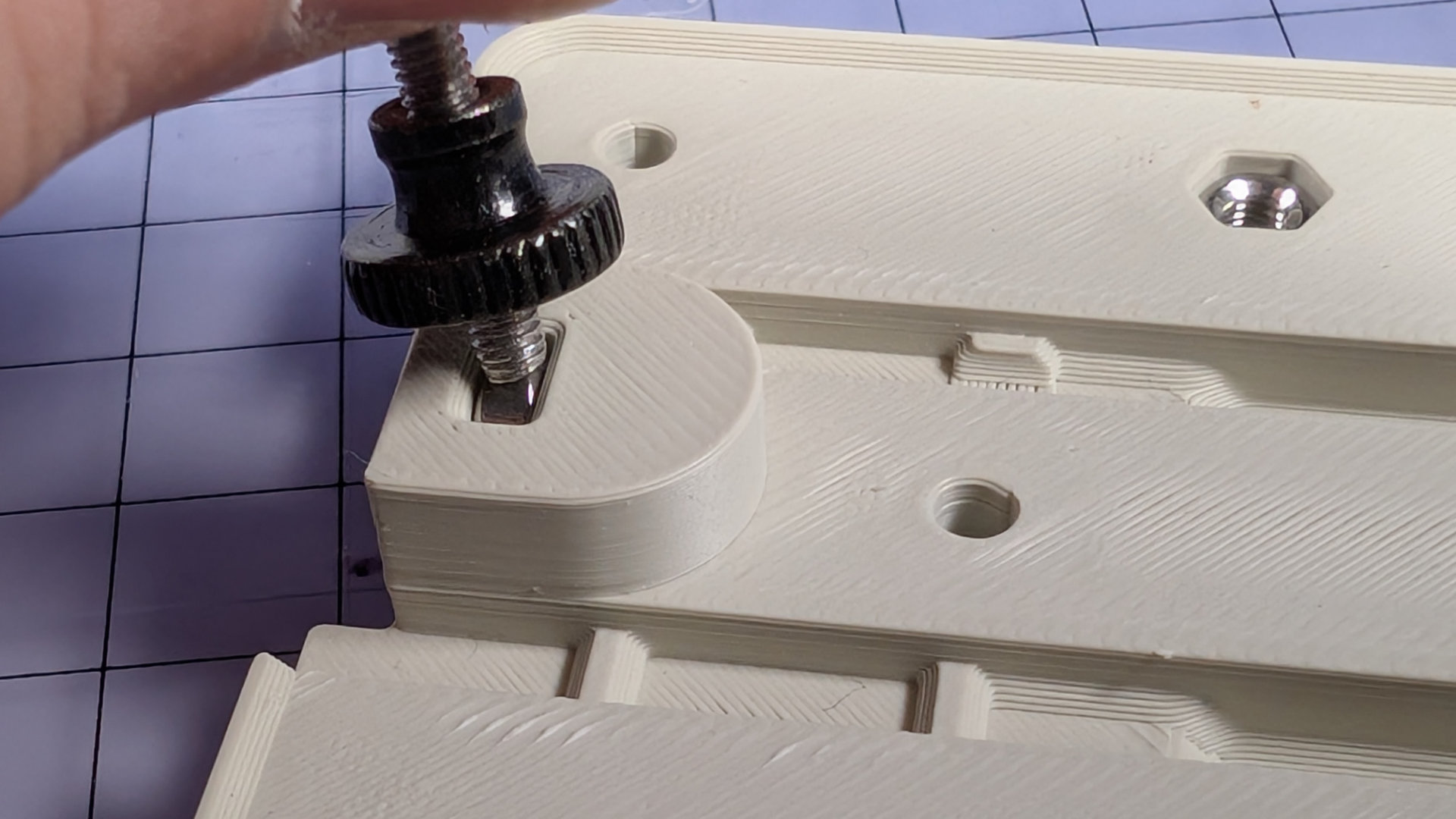
For setting the nuts, I found it best to make a little tool like this, out of a ~30mm M3 machine screw and two thumbwheels. The lower one is inverted, allowing adjustment for consistent depth setting. The upper one acts as a handle and bigger surface to push on.
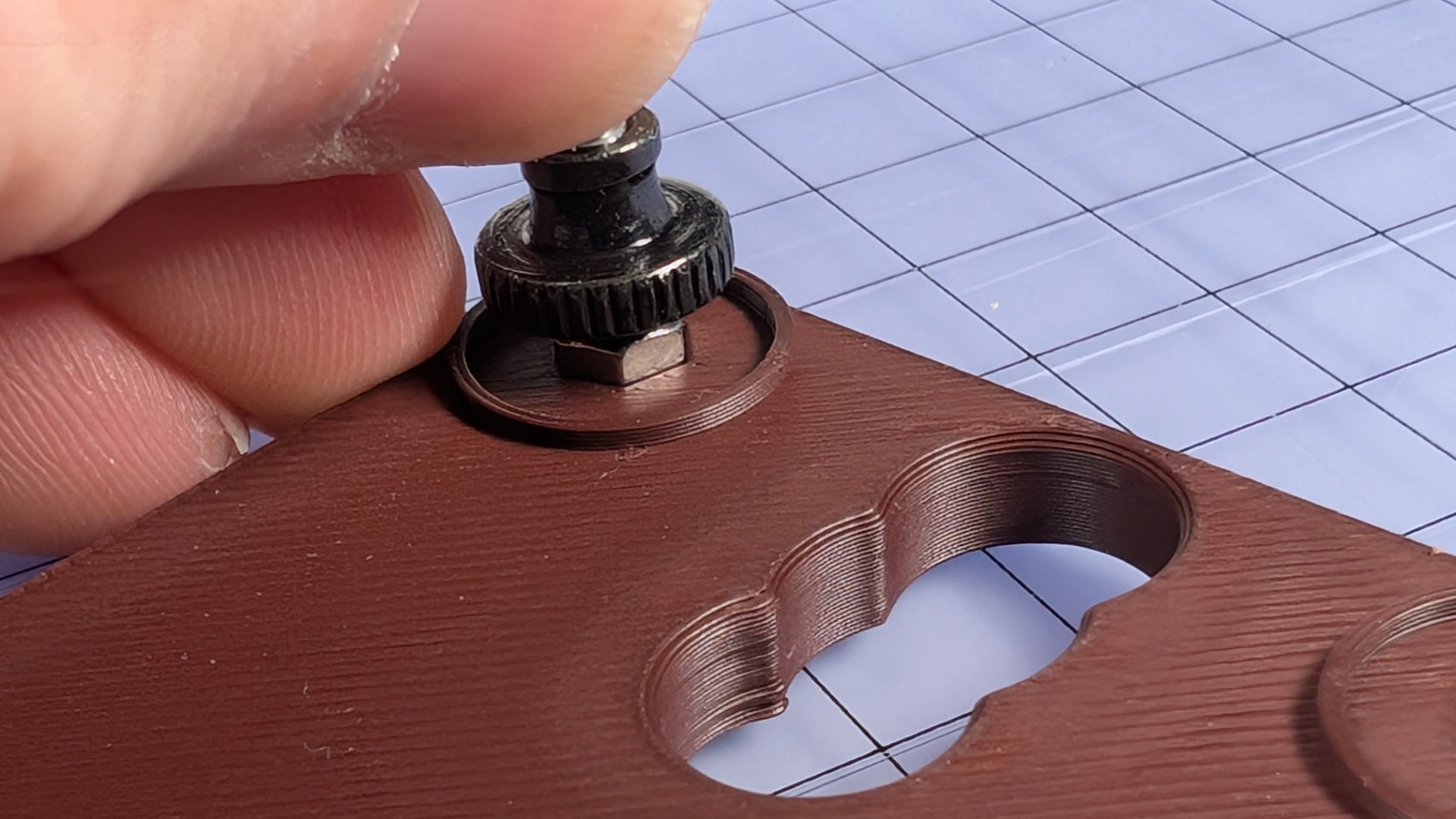
First, the bottom cover. Spin a nut onto the end of the setter, align it over a hexagonal hole, and push down hard. Spin the tool out, and you have a threaded hole in the part. As long as the nut is most of the way home, that's fine. We'll send it deeper the easy way, soon.
The hexagonal holes in the print should be a tight push-fit. If not, for instance if the tolerances of your prints and nuts make them a loose fit, use a little bit of superglue or epoxy to fix them at the bottom of the hex holes. If you don't, loose nuts can fall and stick to the bumper feet that will later cover them. They'll be out of reach of the M3x12 screws, and you'll have an annoying time removing feet from your bottom to fix that.
If the nuts are a good fit and stay put, we'll now pull them tightly to the bottom of the holes. Flip the bottom cover over, and put the baseplate down on top. Spin four M3 machine screws into the corner holes, and tighten them down firmly. This is the one part of this build where the leverage of an L-shaped hex key is useful.
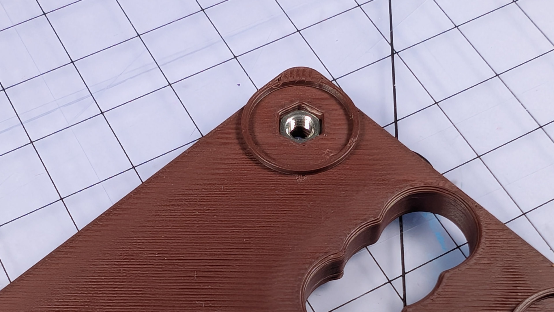
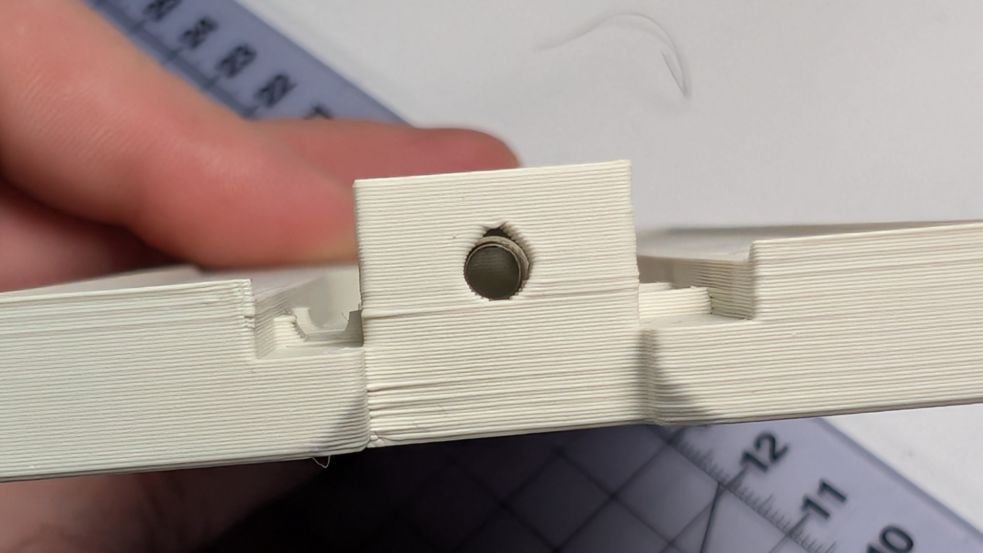
The nut has now been pulled deeper:
It's very important that these nuts are firmly in place, at the bottom of their holes.
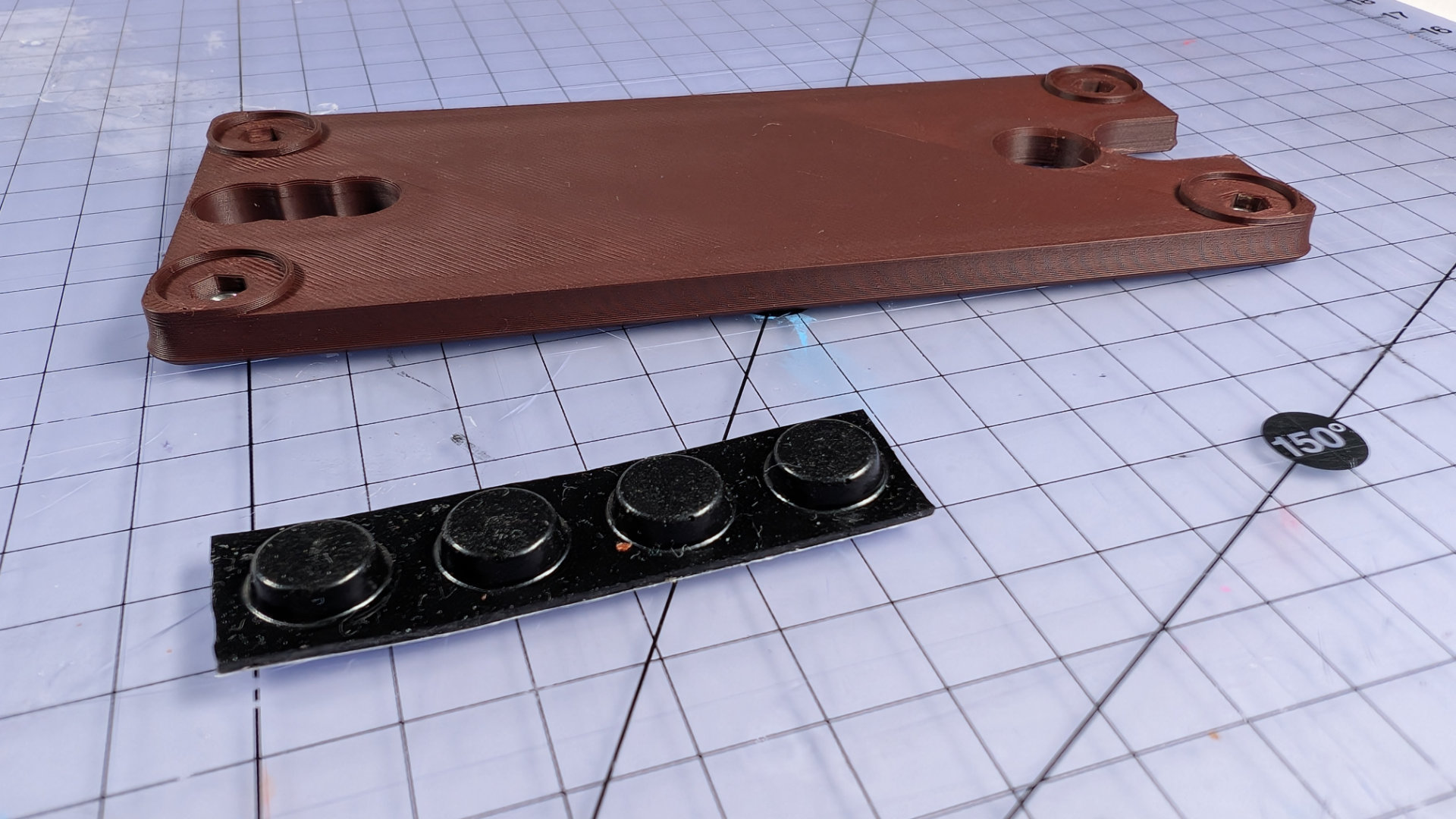
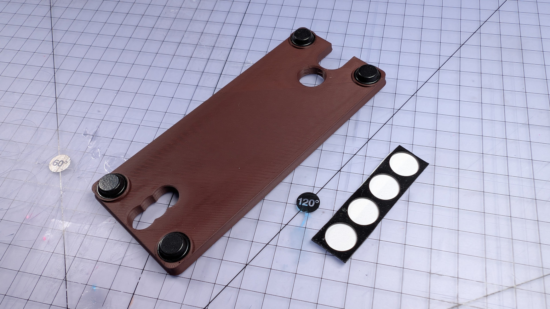
Remove the screws and set them aside. Now take four 12.7mm adhesive bumper feet, and attach them to the bottom cover, concealing the nuts.
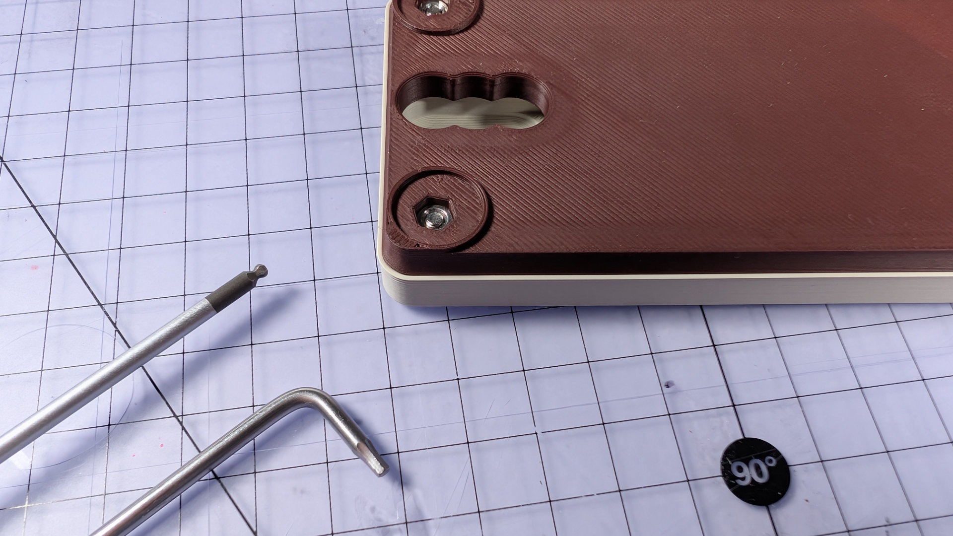
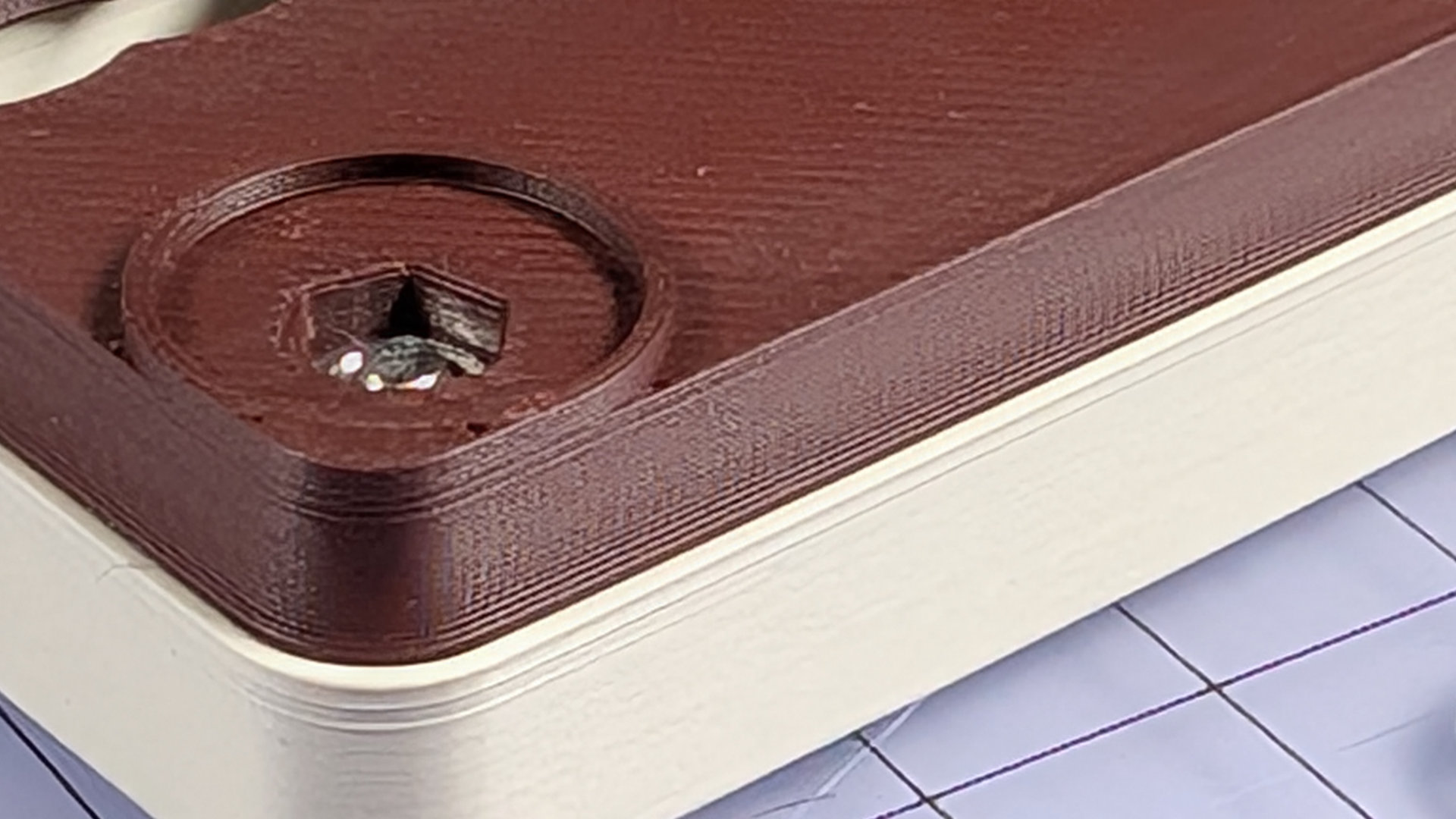
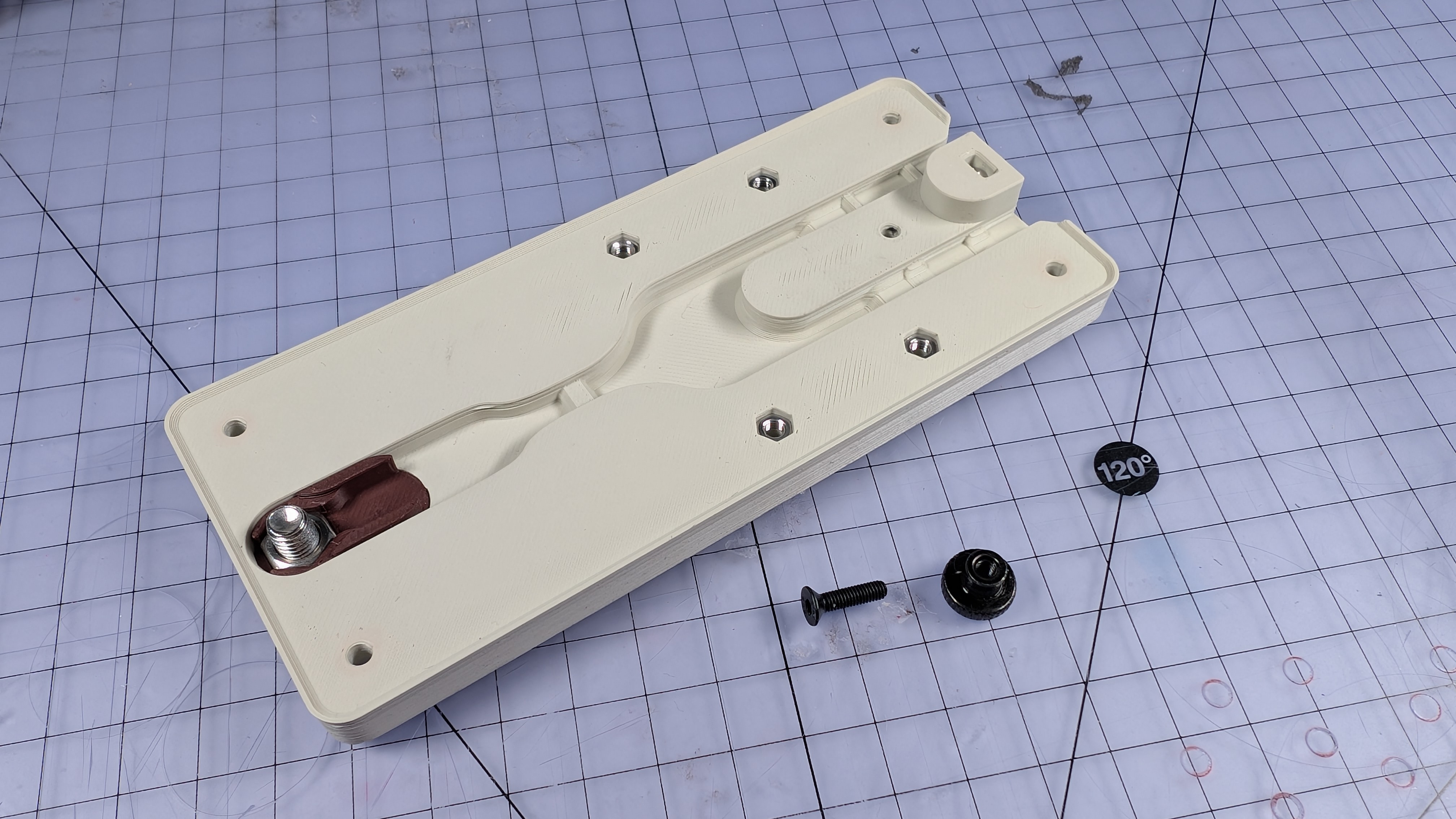
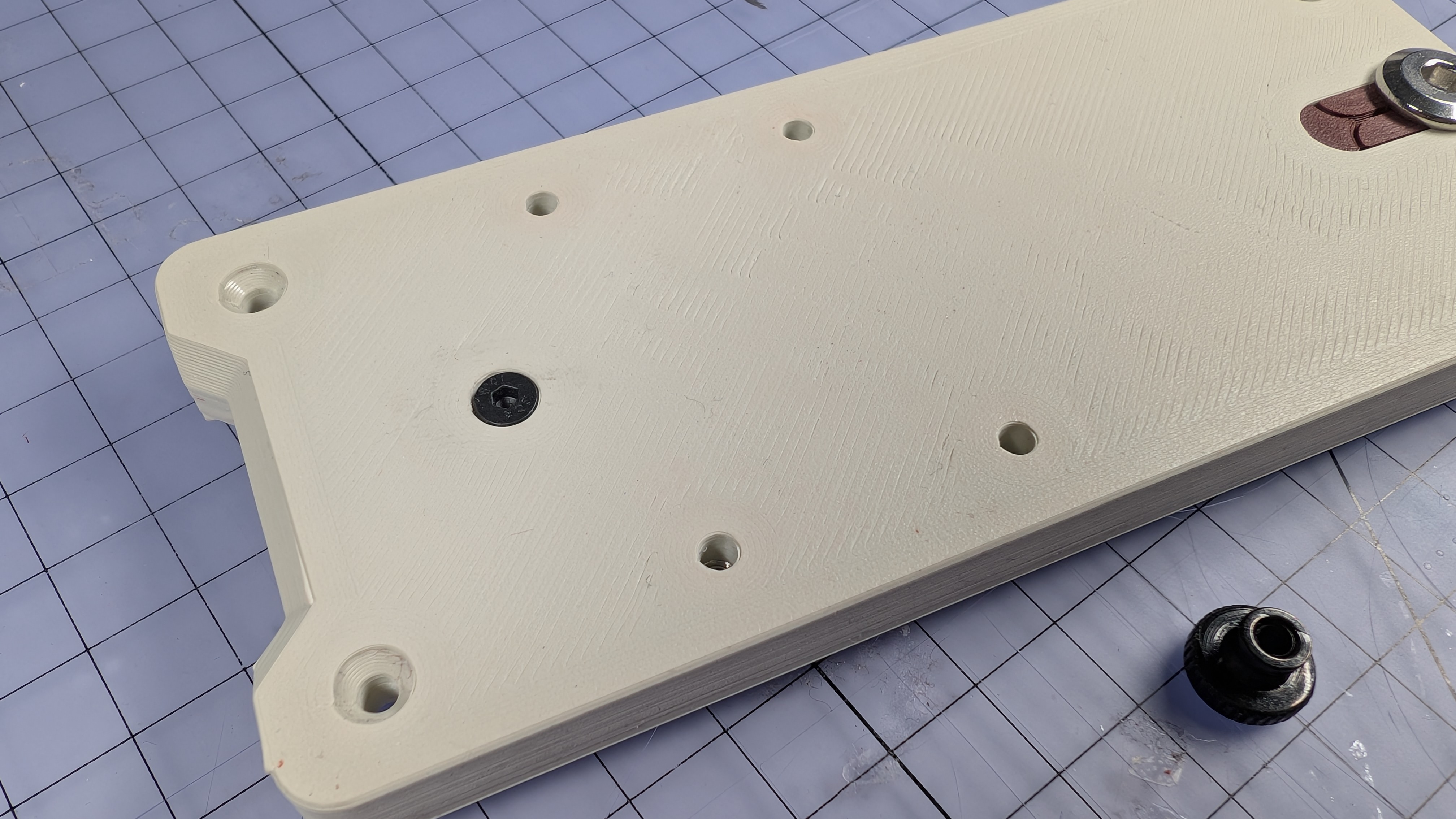
That's the bottom done. Now insert four nuts into the baseplate using the nut-setter.
These nuts will sit much closer to the top surface of the baseplate than the ones in the bottom cover, so there's no need to pull these ones tight from above. As long as you give them a good push with the nut-setter, any fixings passing through the baseplate later should reach them.
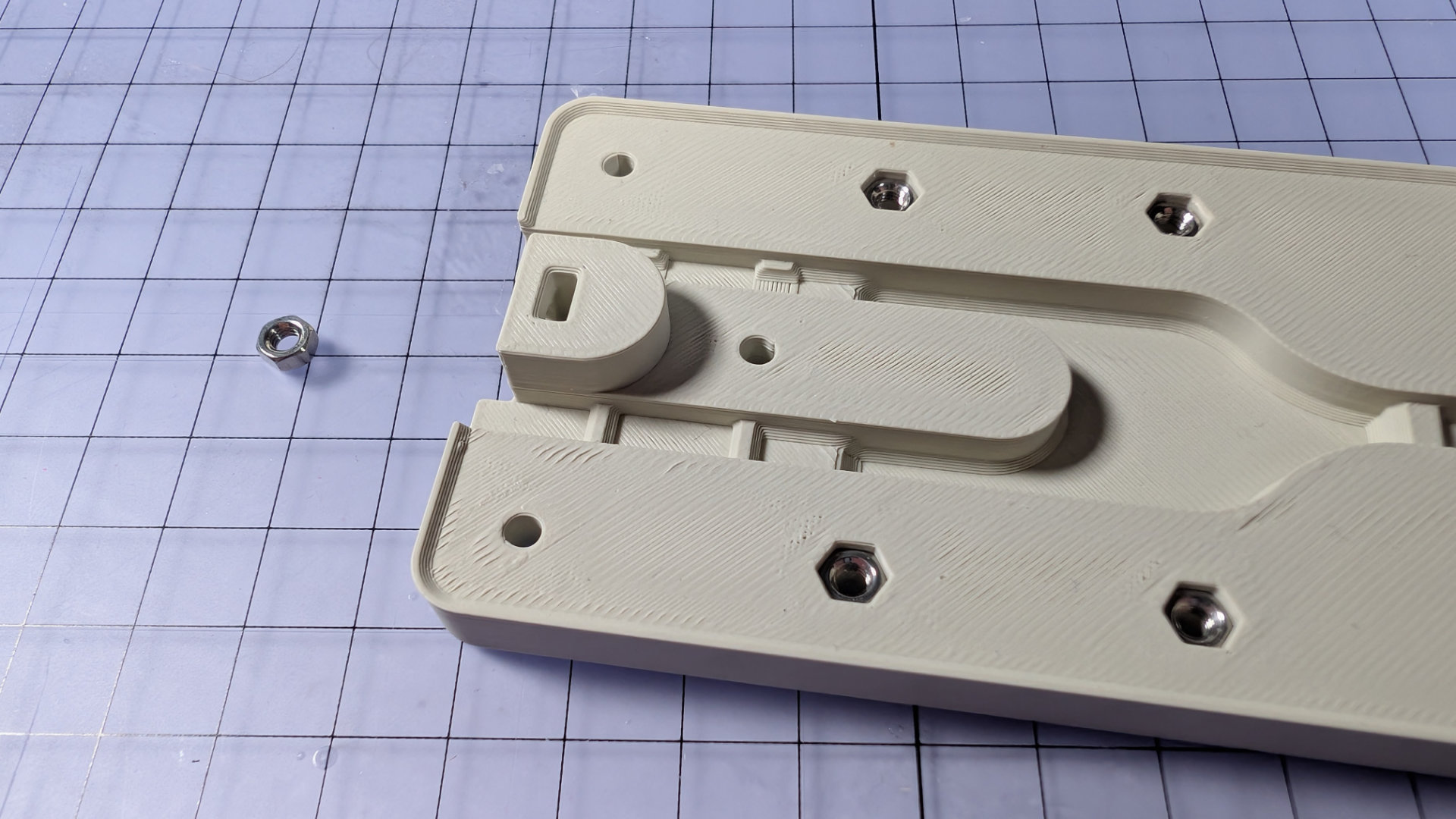
You might have noticed a fifth nut in the picture above. Dis nut goes in the slot near the back, and is the third fixing point for the spoon plate.
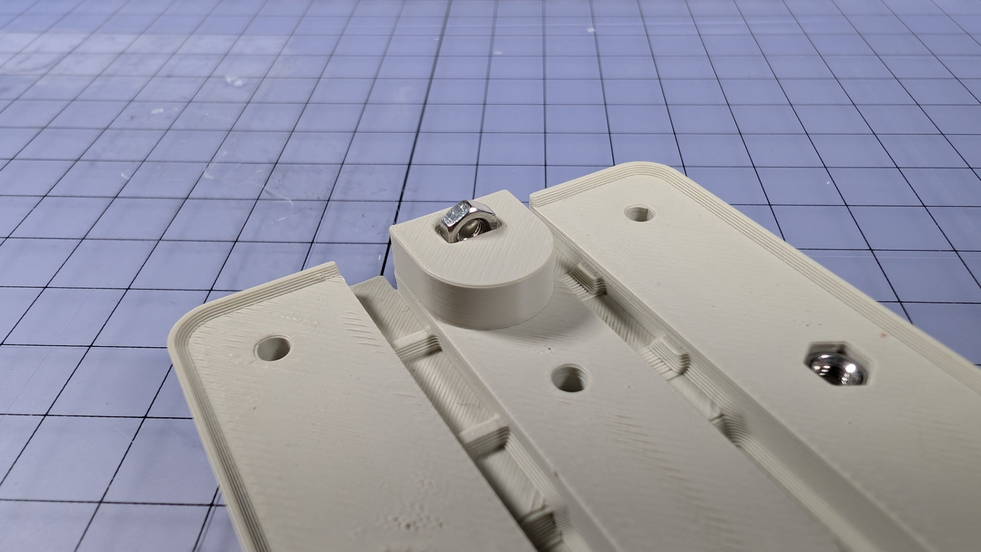
Tweezers are useful for getting it aligned and started. This should be a tight pushfit; the side and end of the nut-setter are useful for making sure this one gets all the way to the bottom of the hole.
Make sure the nut hole is aligned with the one in the back of the baseplate.
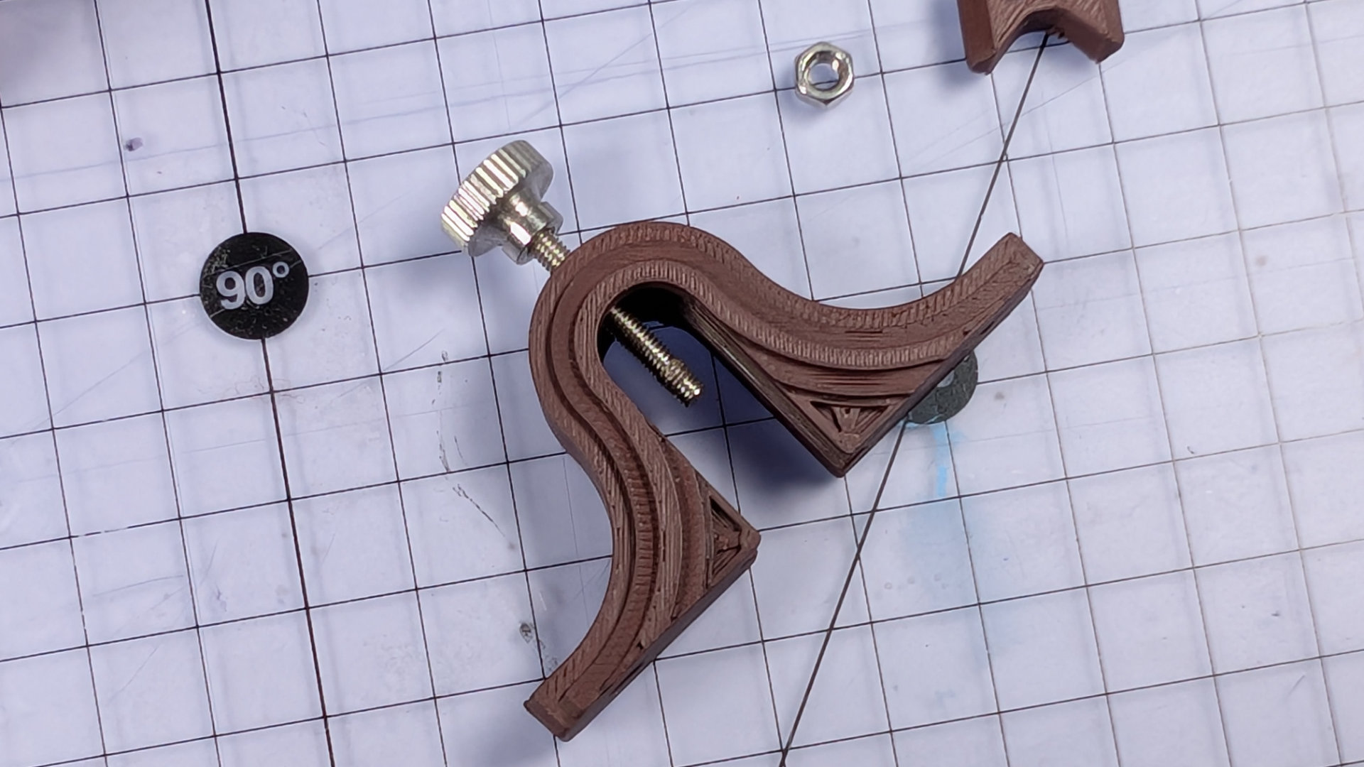
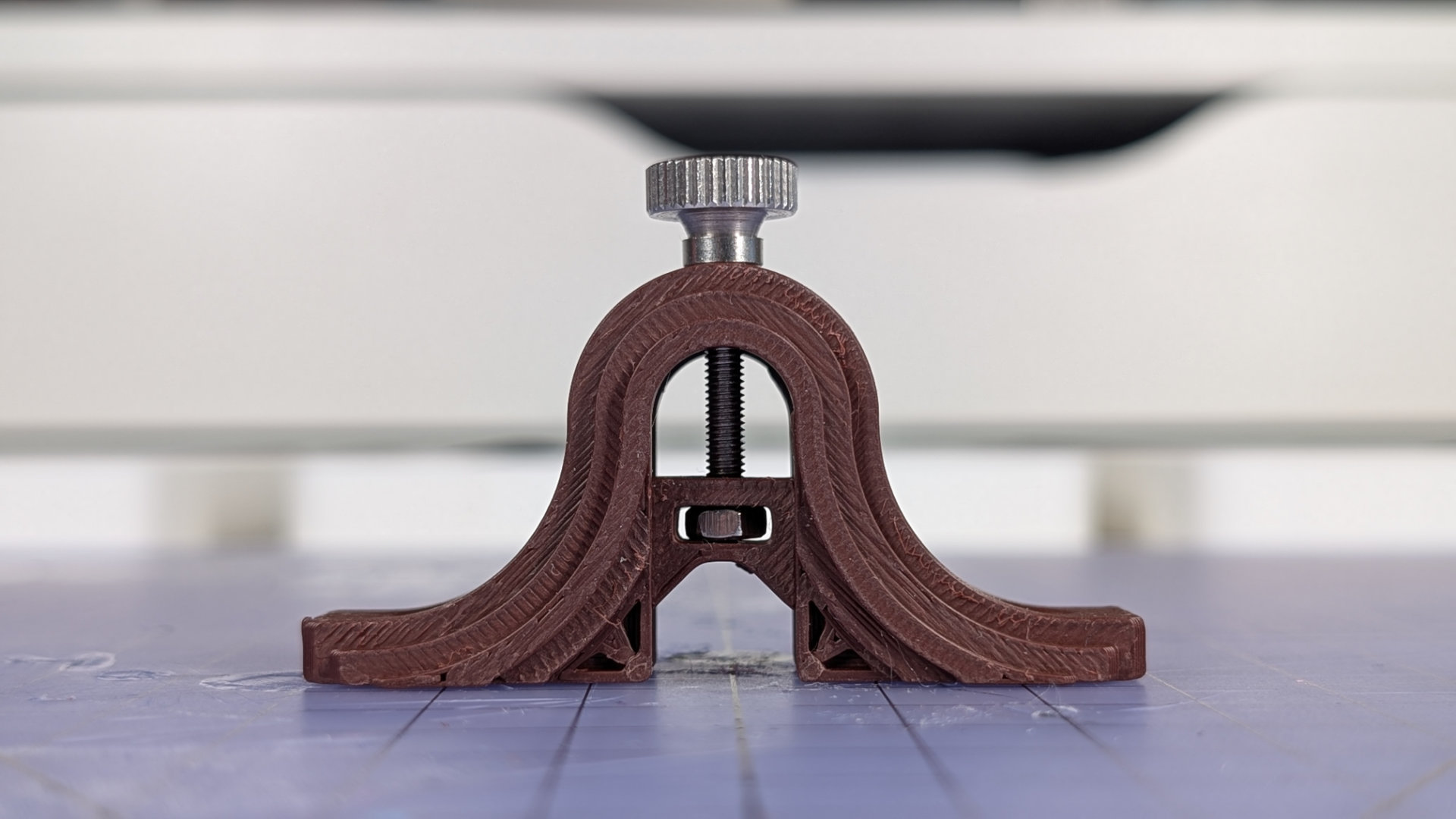
Assemble Travel Adjuster
The next step is to assemble the travel adjuster. To work properly, this requires a heatset insert and threadlocker. You could replace the knurled thumbscrew with any M3 machine screw of sufficient length, but having this adjustable by hand, rather than needing a tool, is a nice finishing touch.
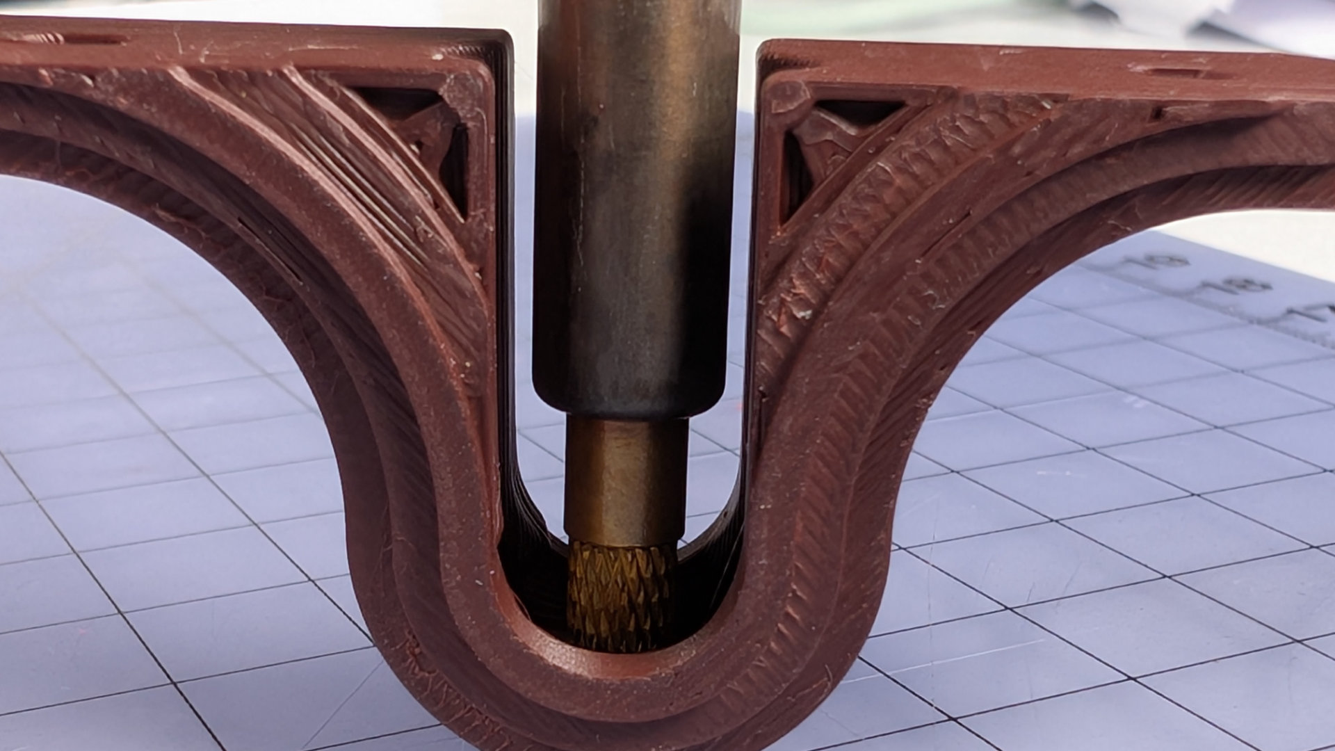
First, from the underside, place the brass insert into the hole at the top of the travel adjuster.

Now use the M3 brass insert tip in your soldering iron to melt the insert into place. The inside faces of the travel adjuster can really help you keep the iron vertical.
On top, the hole may require a little cleanup with a scalpel.
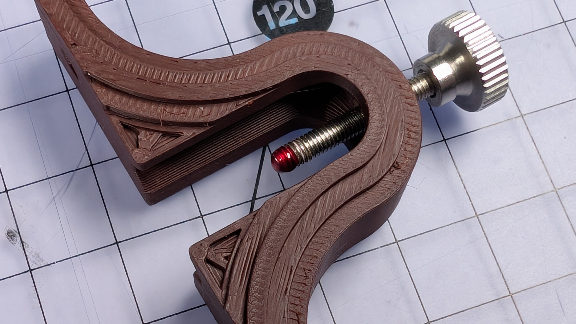
One the melted plastic has fully hardened, and not before that point, drive the thumbscrew in for about half its total length.
Add a dab of red threadlock to the tip of the screw. It won't bind any metal parts to PLA ones. Blue threadlock is insufficient here, it has to be the kind that requires heat to release (heat or, proportionally to the fixings, a lot of brute force). Having built dozens of these, I've found it's better to have a tiny bit too much threadlock than not quite enough.
Now pop an M3 nut into the slot of the slider, and push the slider into the base of the travel adjuster. A finger under the back to stop the nut falling out works fine for this stage. The image shows tweezers here instead, because my untrimmed thumbnail looked pretty gross in these close ups.
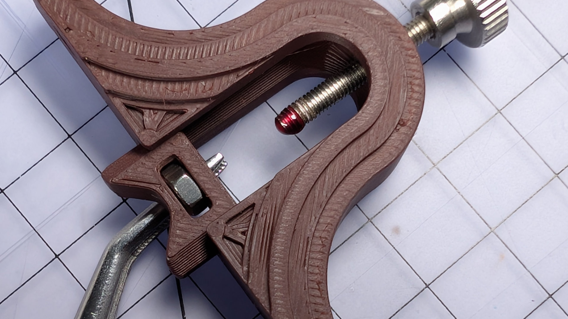
Slide it into place and, holding the nut still with finger and thumb, spin the thumbscrew down into the nut until it bottoms out. You can see here the slot has a little bit of clearance for the nut. If you like, you can back the thumbscrew off a reeaaally tiny little bit to preserve some of that. I prefer to leave the screw touching the bottom of the slot, as shown below.
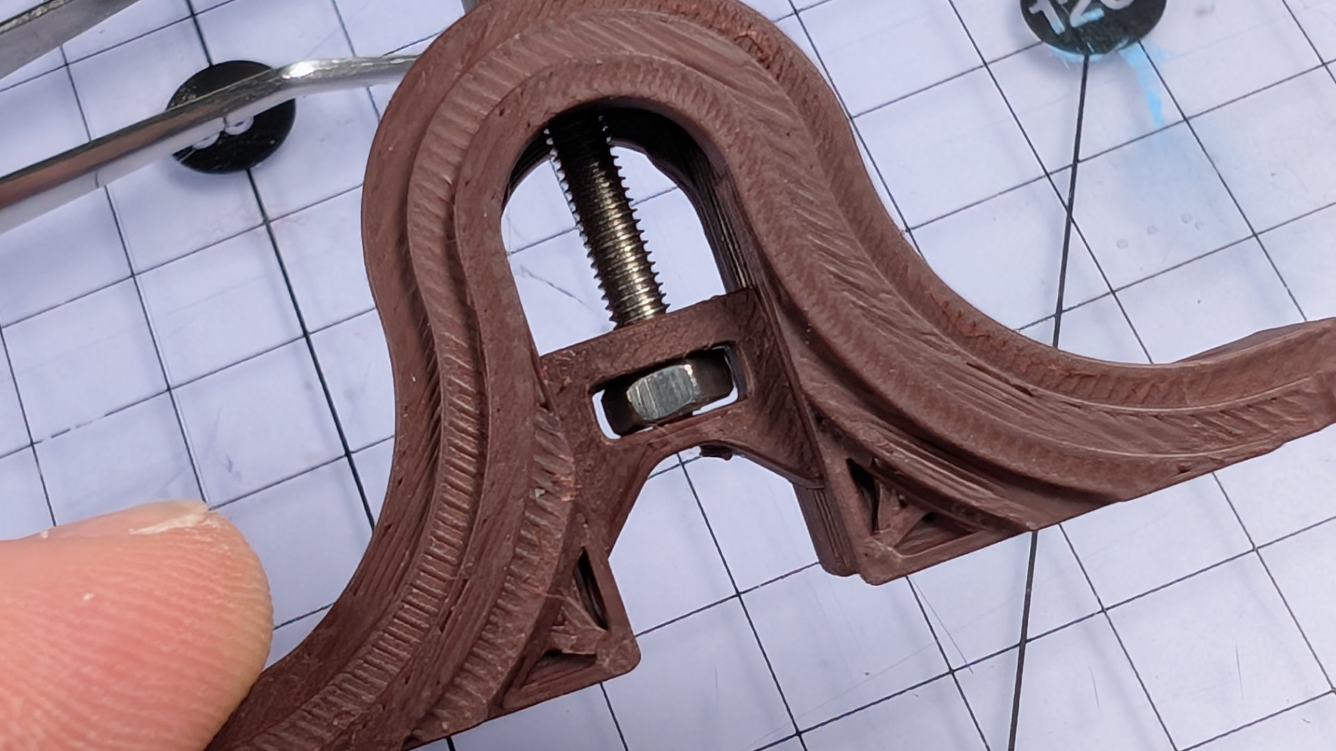
Backing it off at this stage can lead to noticeable vertical slop in the travel adjustment, every time the spoon slams back into it. If instead you leave the screw tightened against the bottom of the slider while the threadlock dries, just through use the end of the screw will quickly wear whatever clearance it needs into the plastic.
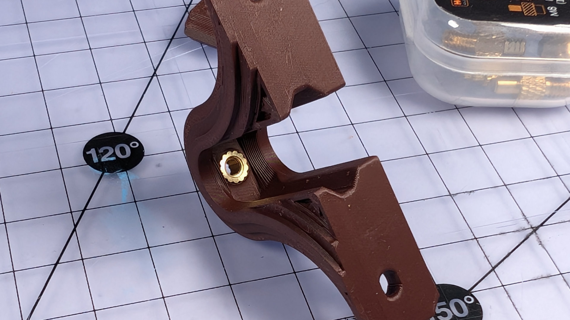
That's the travel adjuster fully assembled, and you must now leave it alone until the threadlock has dried. When you come back to it in a little while for final assembly, it'll be fully set and you can fiddle with it to your heart's content. Right now, spinning that screw will just make the travel adjuster more likely to have slop or come apart later on.
Fabricate Wiring
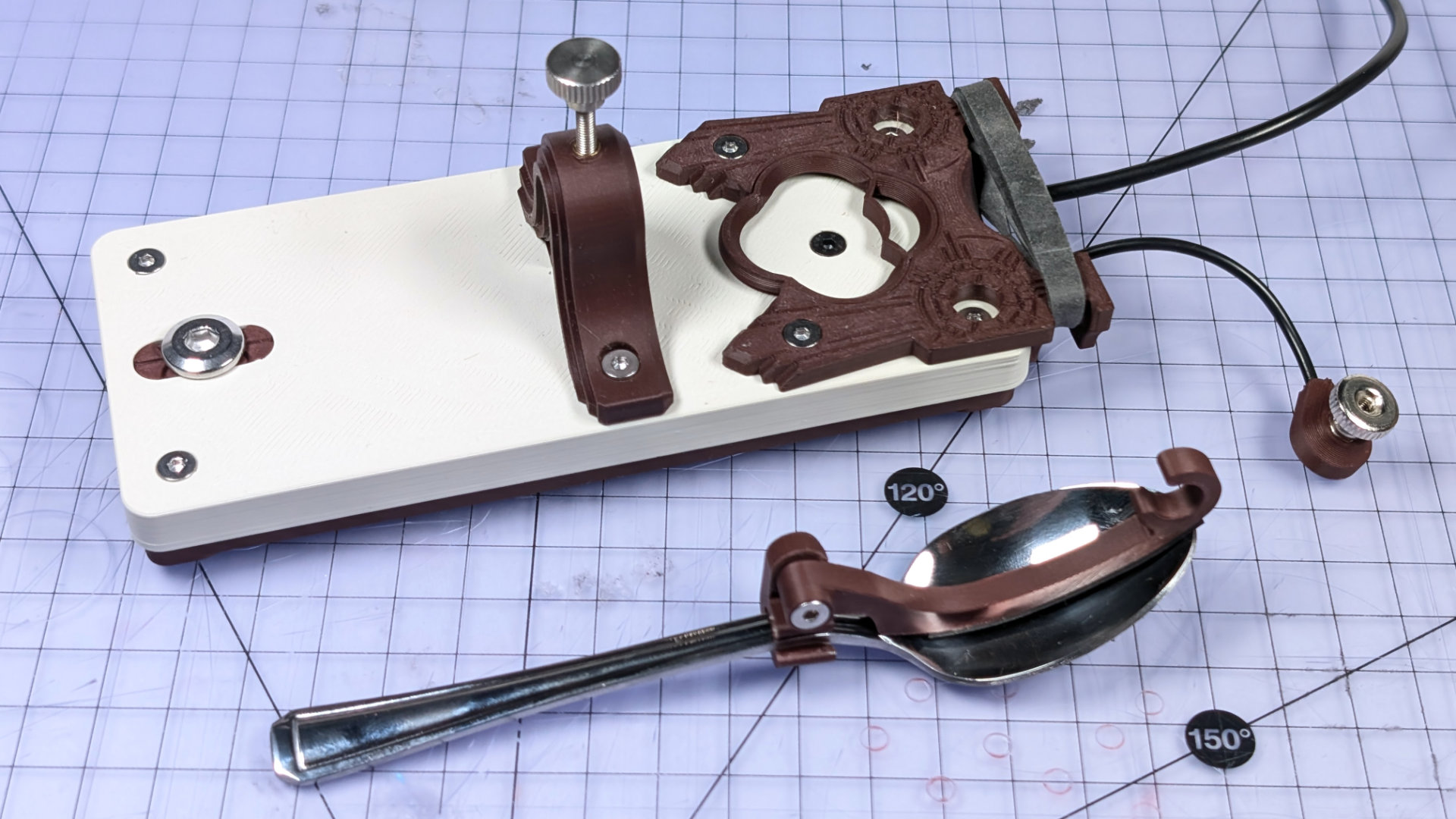
Now we'll build all of the wiring at once. It consists of a trailing 3.5mm mono socket, with one lead joined to a crimp terminal, the other to a magnetic contact.
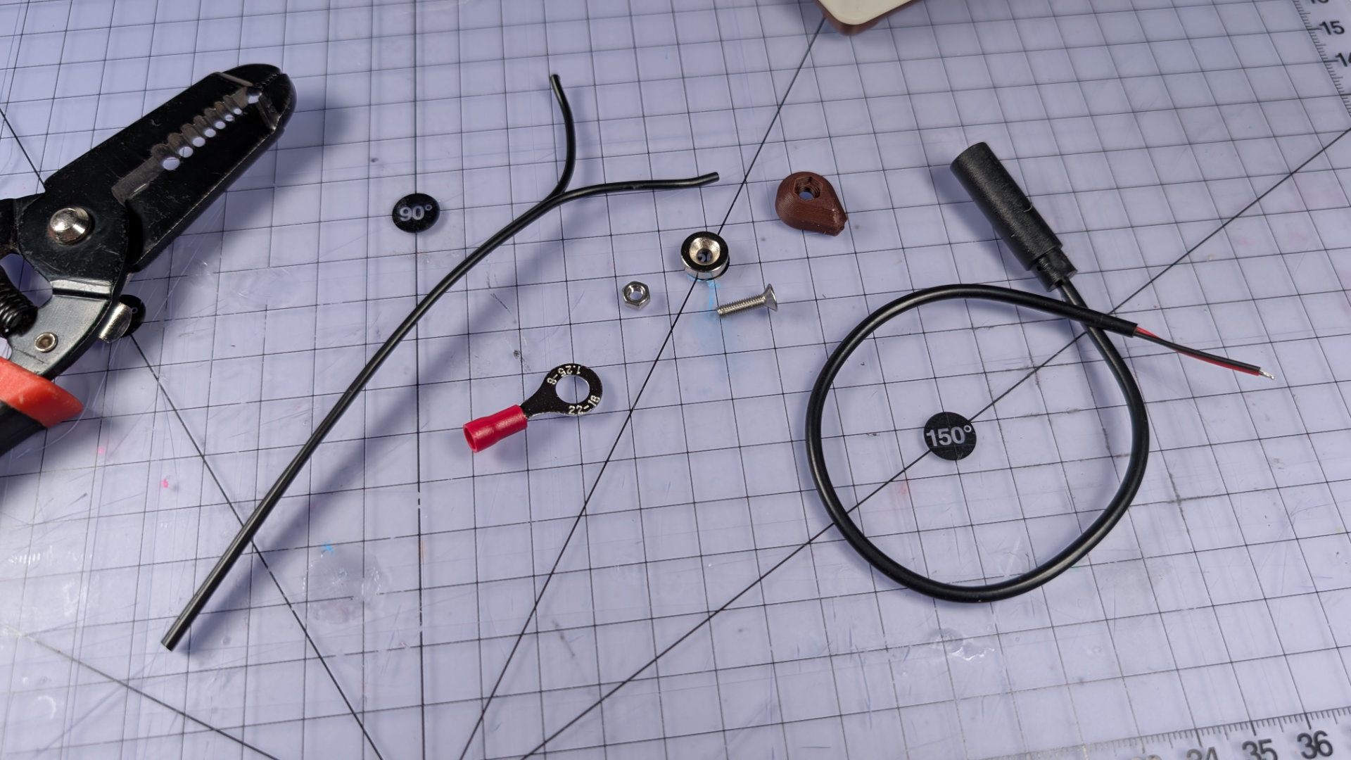
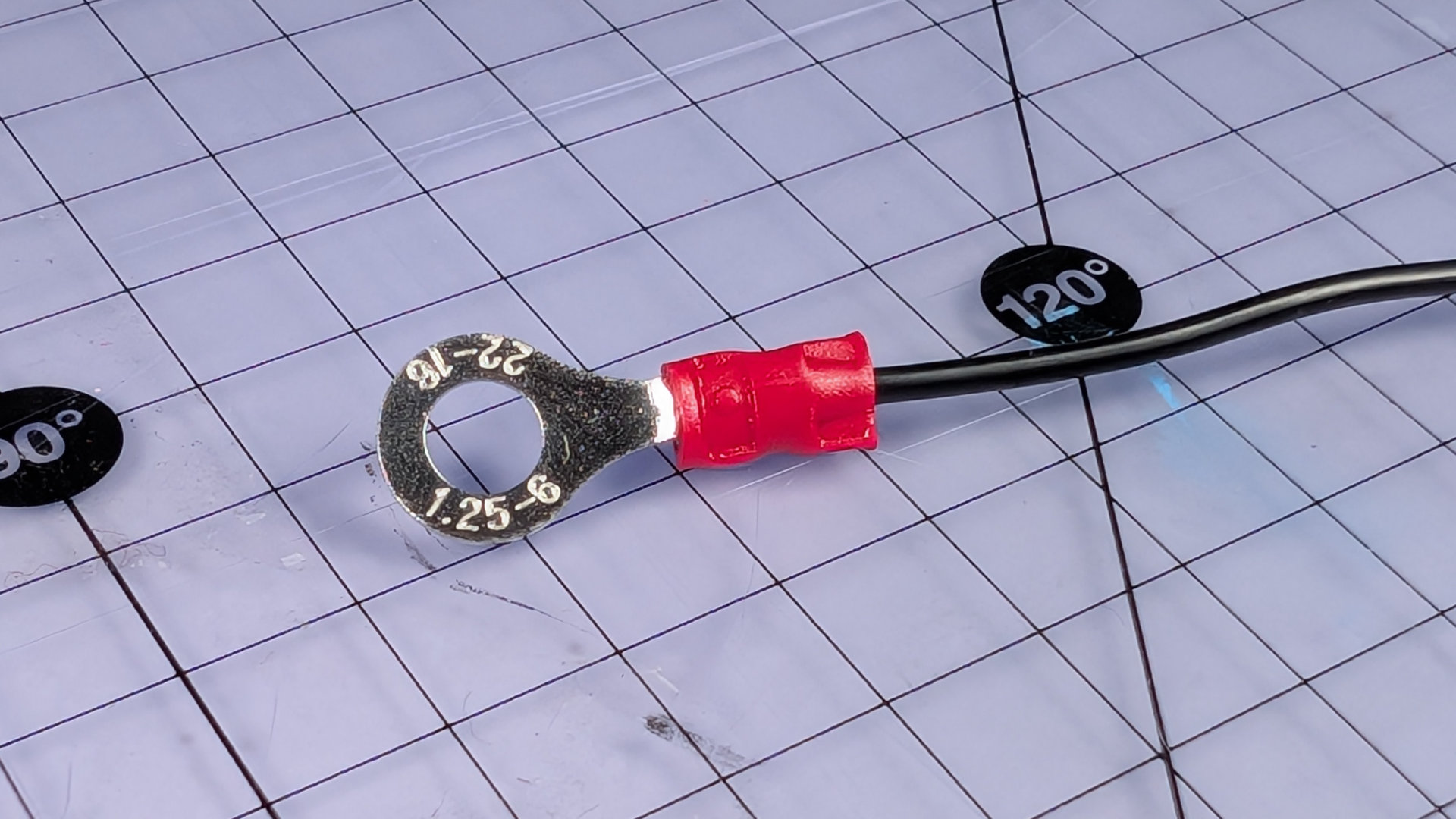
Cut two lengths of 20AWG stranded wire, 65mm and 190mm. The short piece is for the crimp terminal, the long one for the magnetic contact. Strip the ends of the short piece and crimp it.
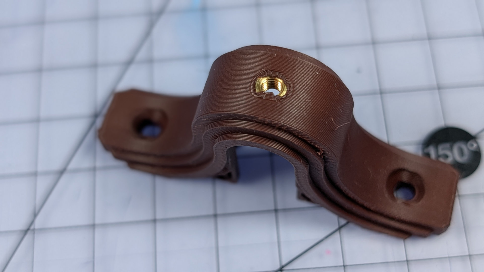
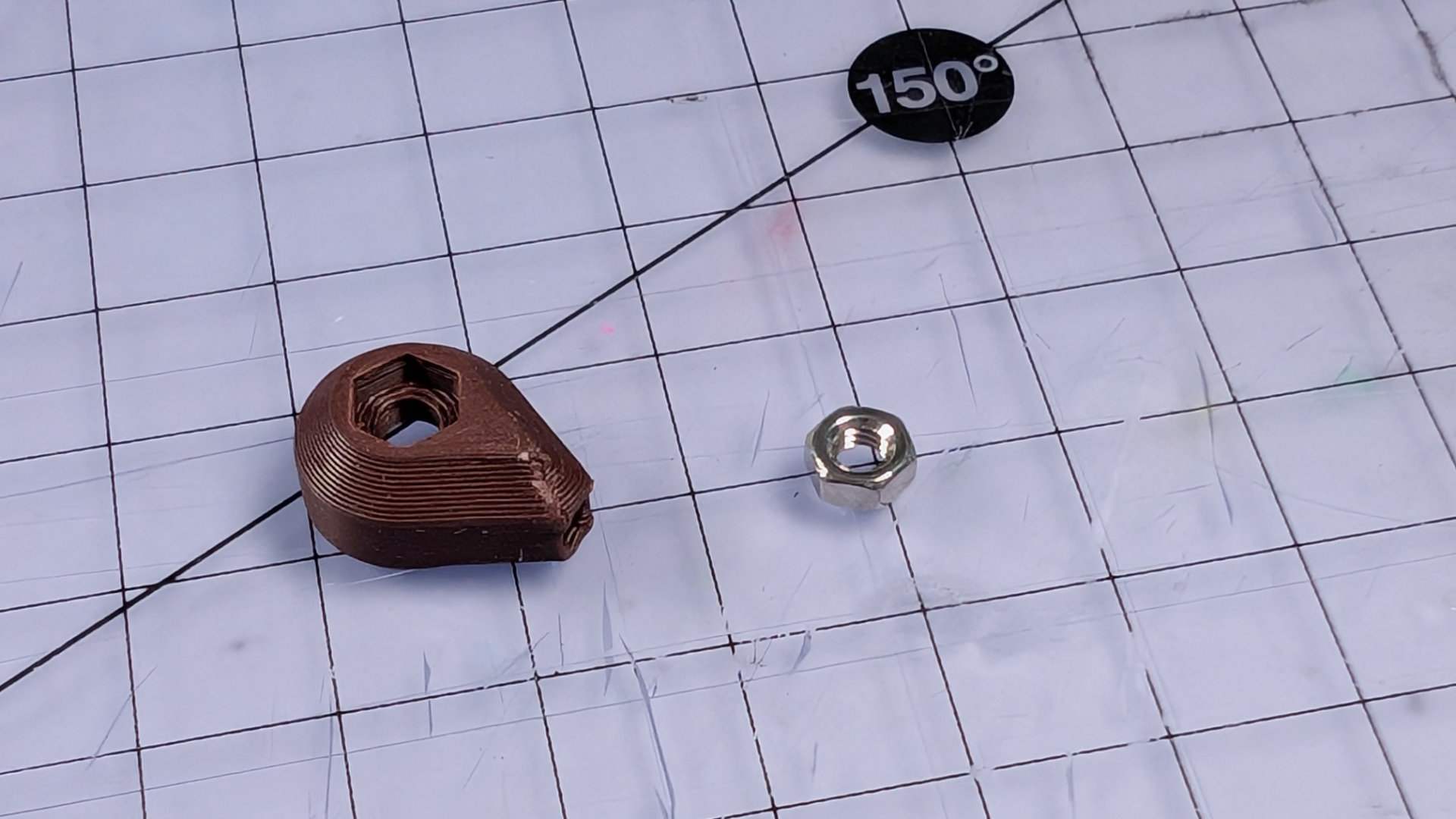
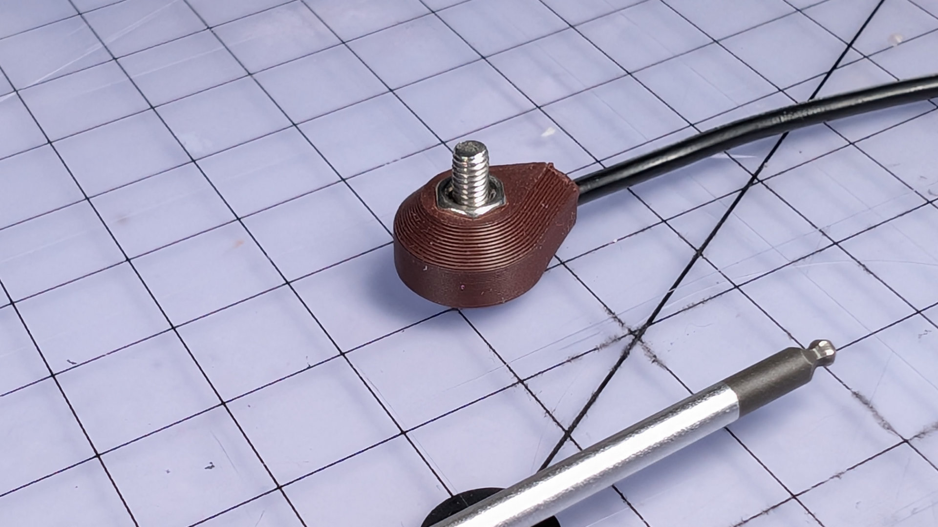
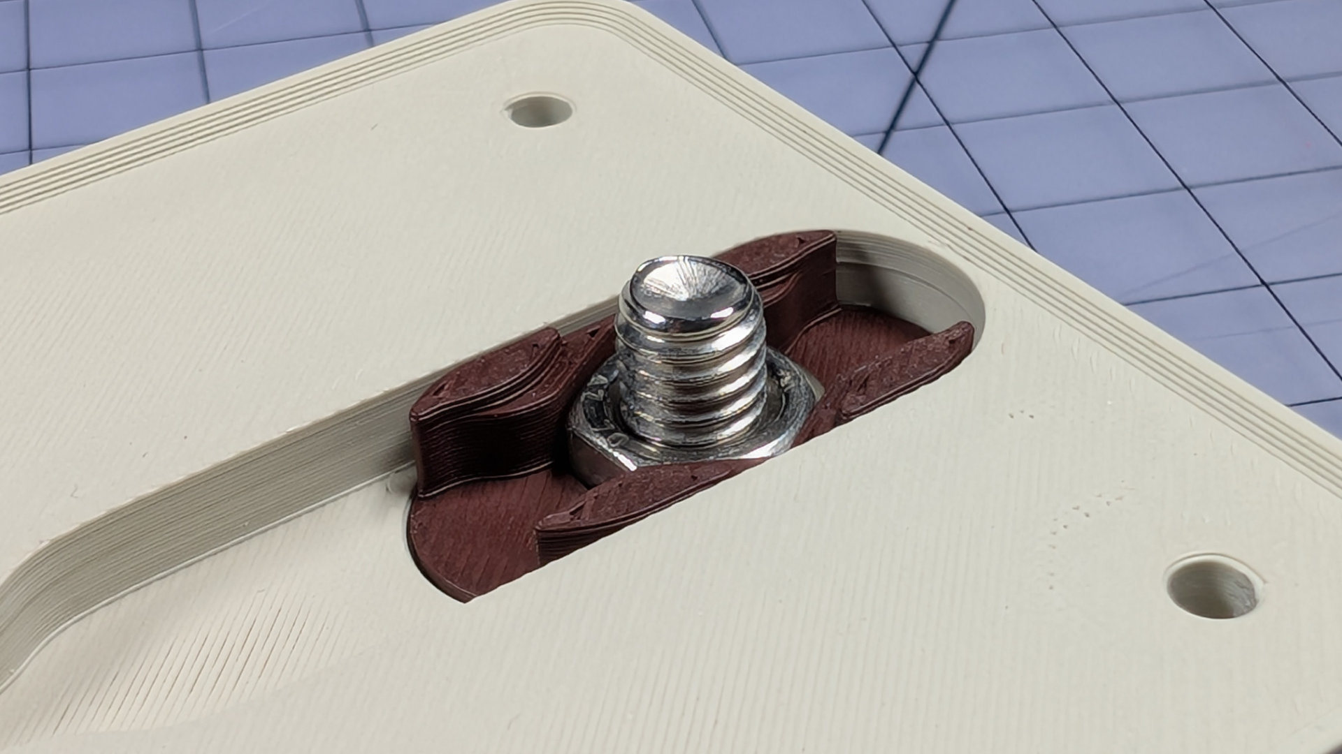
Now take the magnetic contact body and push the hexagonal hole down onto an M3 nut to embed it.
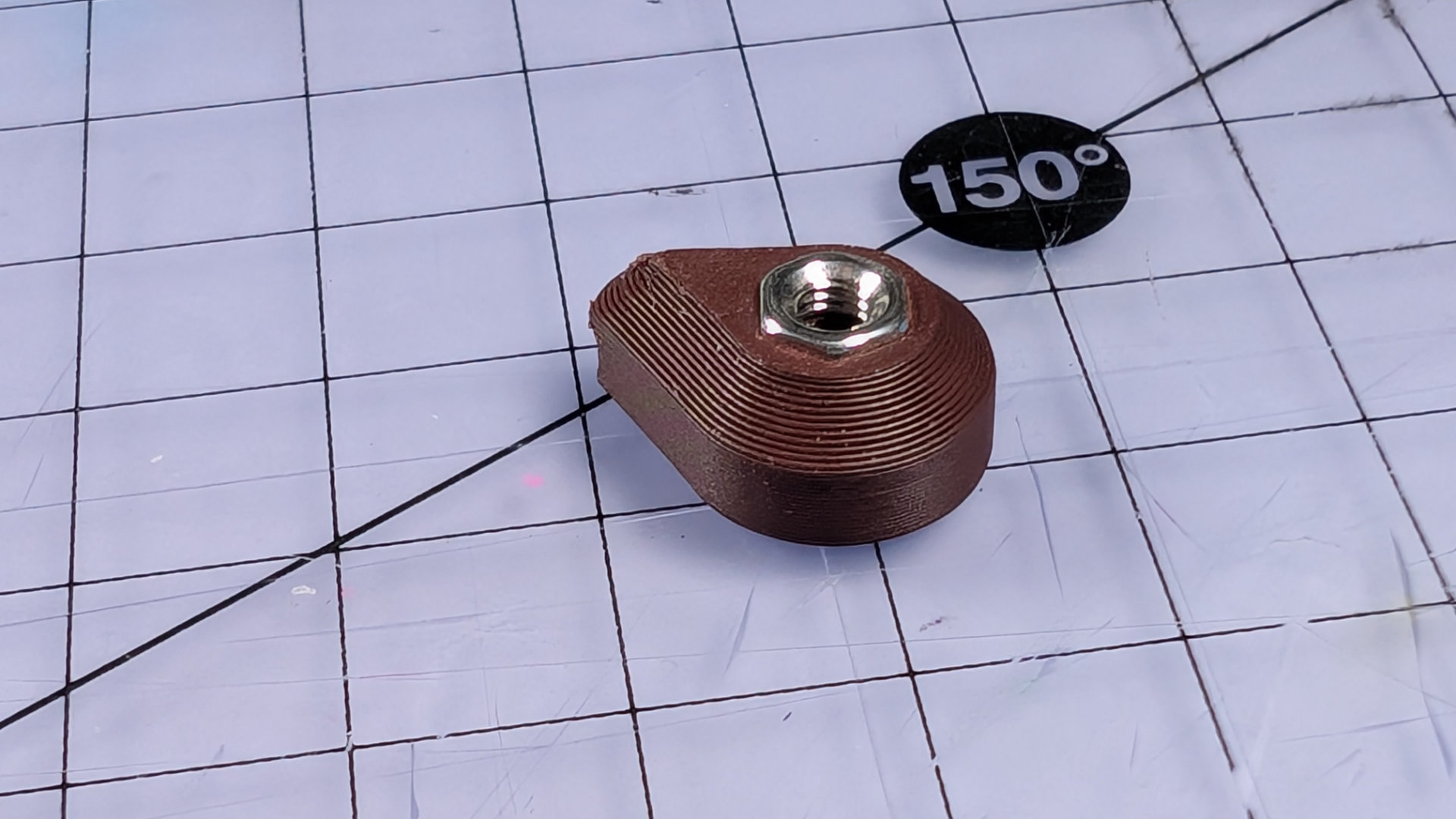
Take the 190mm wire, and strip just enough from one end to solder it later. At the other end, strip around 2.5cm (an inch) of insulation, then twist the exposed strands together firmly. Taking the magnetic contact body, feed the bare wire through the small hole like this:
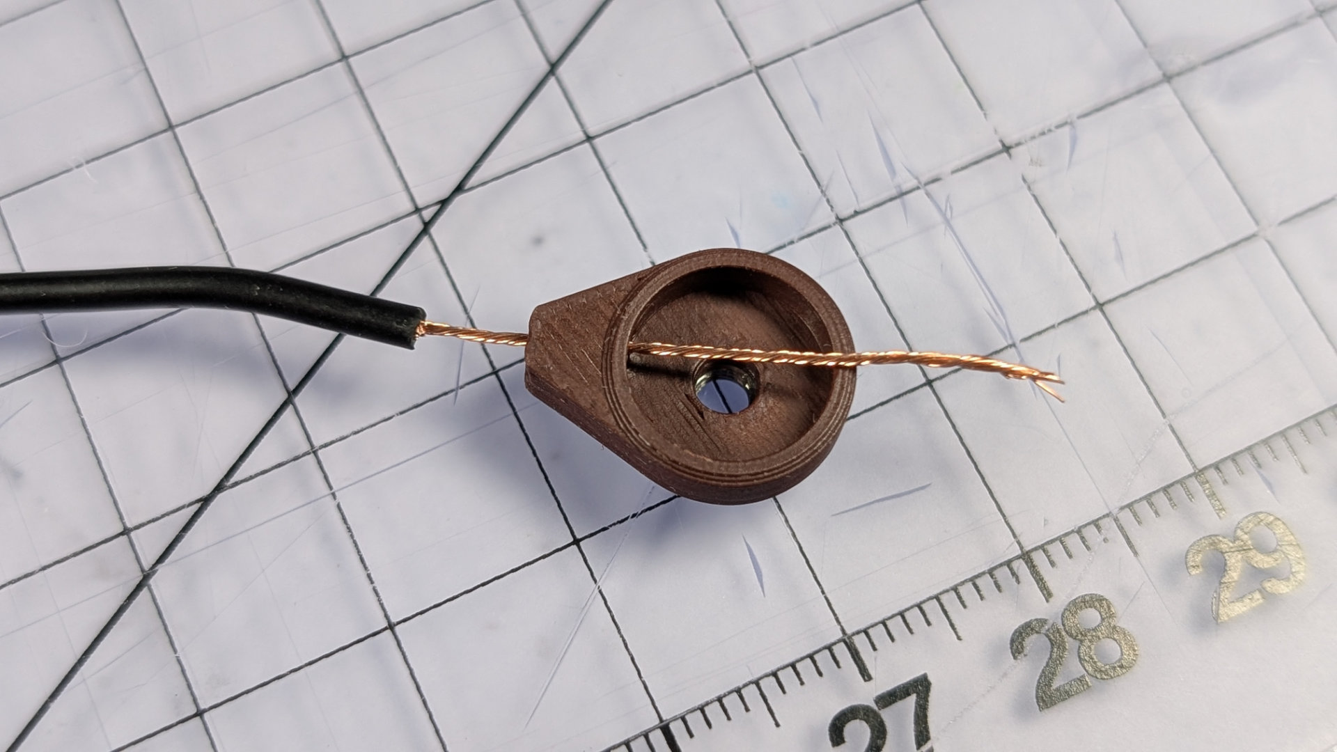
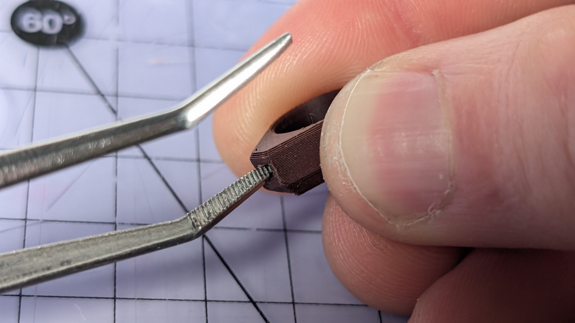
Next you need to push the insulation all the way into the hole. 20AWG wire should be a push fit. Tight is good, but if tolerances make it too tight, the ends of some tweezers like these can ream the printed part until you get a better fit.
You want the end of the wire insulation to get close to the inside hole, but not advance into the main cavity. It also needs gluing to the housing in order to stay put, so use a fine applicator nozzle to put a drop or two of appropriate liquid glue through the inside hole here. Be careful not to use too much, or it will wick up the twisted wire.
The correct glue might vary depending on what material your 3D prints are. I favour silicone glue for PLA and PETG, because compared to regular superglue, it seems a little less prone to frosting surfaces.
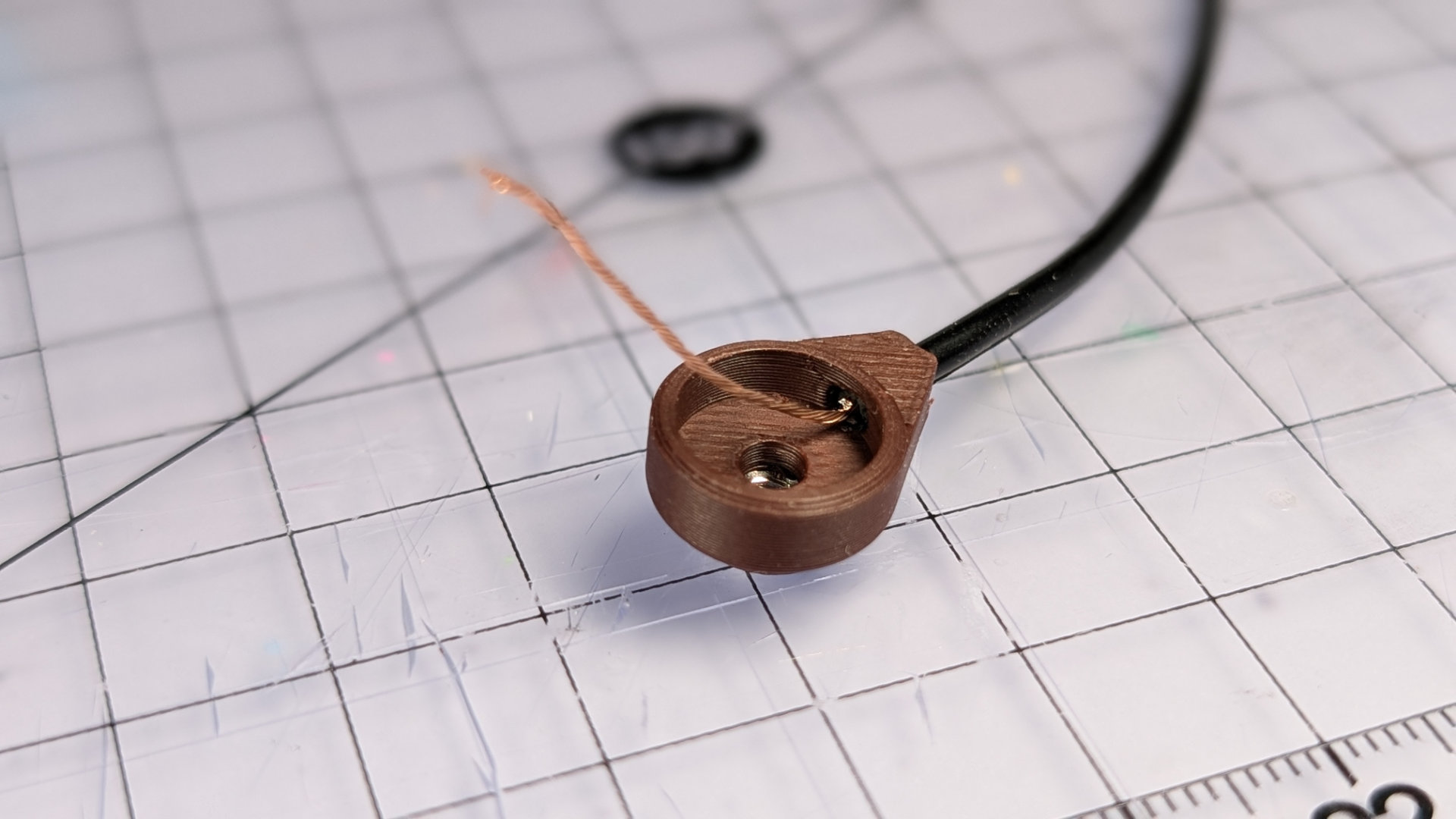
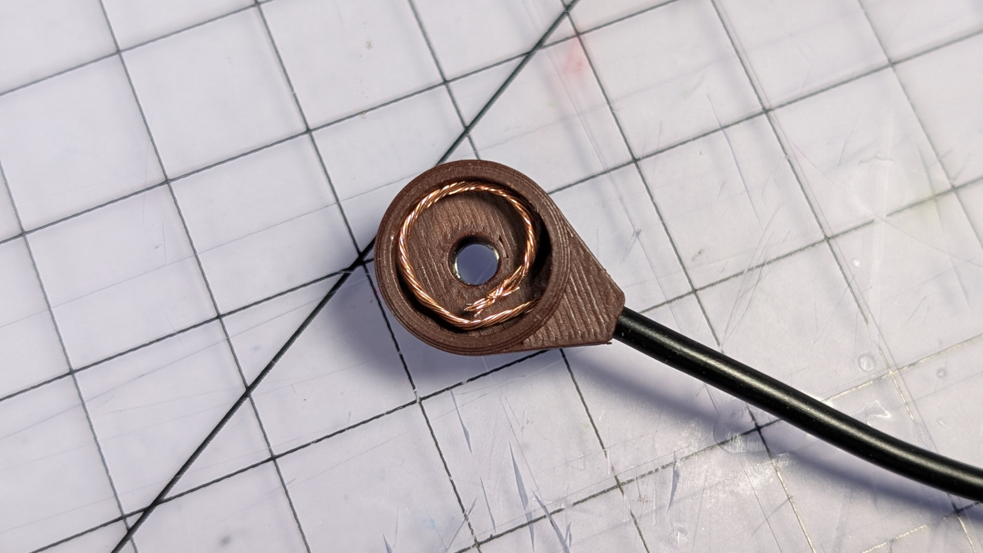
Once the glue is dry, using your tweezers, shape and lay the bare wire around the inside of the cavity. The overlap shown below is good, just make sure the tendril of wire doesn't pass over itself. The magnet will be compressing it all, so we want it to end up as flat and even as possible. I find copper wire tends to be a little better behaved for this sort of manipulation.
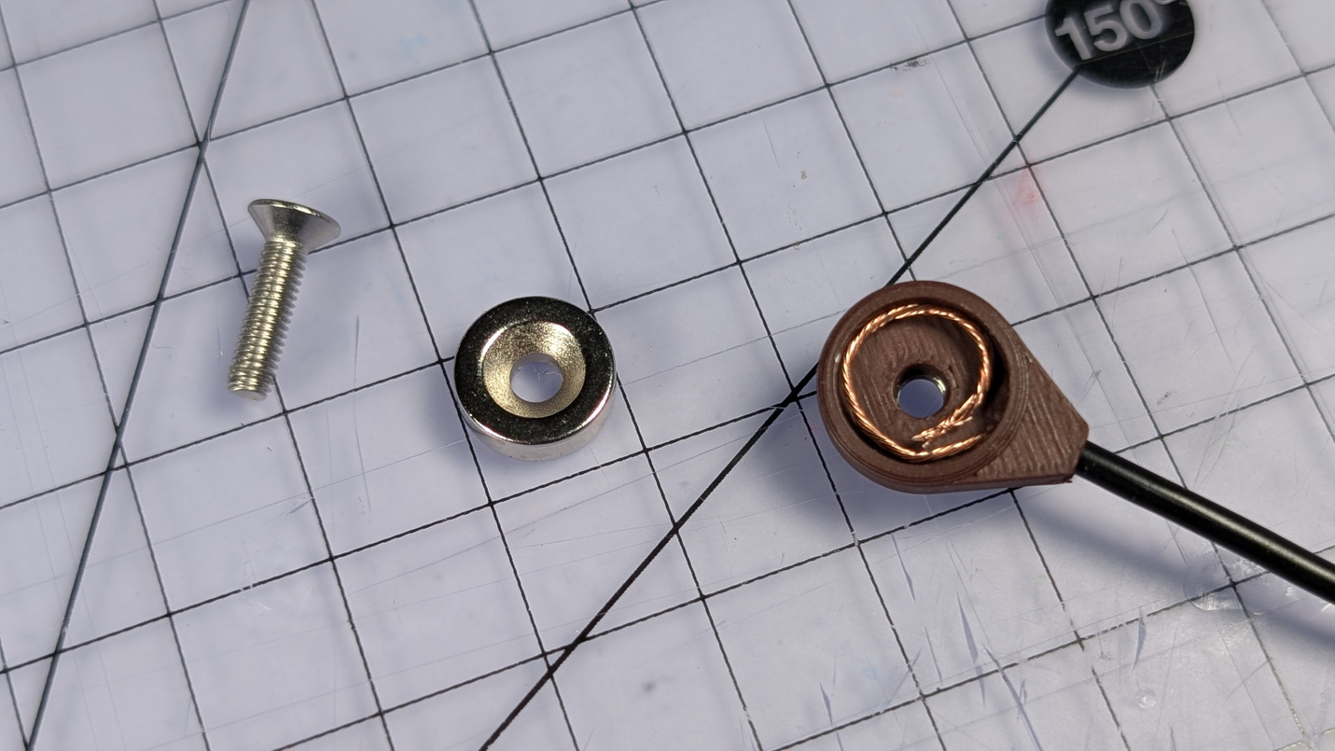
Push the magnet in, making sure the countersunk side is facing out. This might take a little force. Placing the magnet face down on the work-surface then pushing the printed housing down onto it may work best.
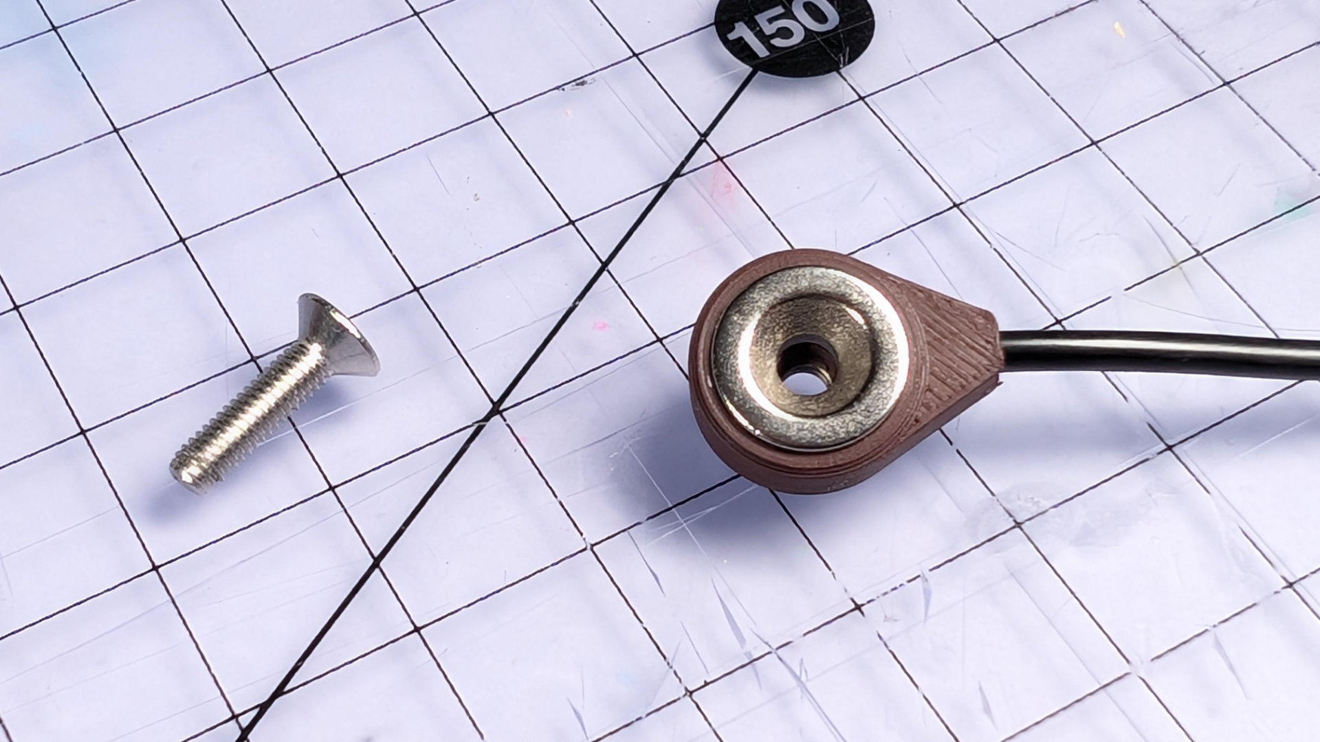
Now bolt it together tightly with an M3x12mm screw. The correct torque rating is 2 micro-uggadugs.
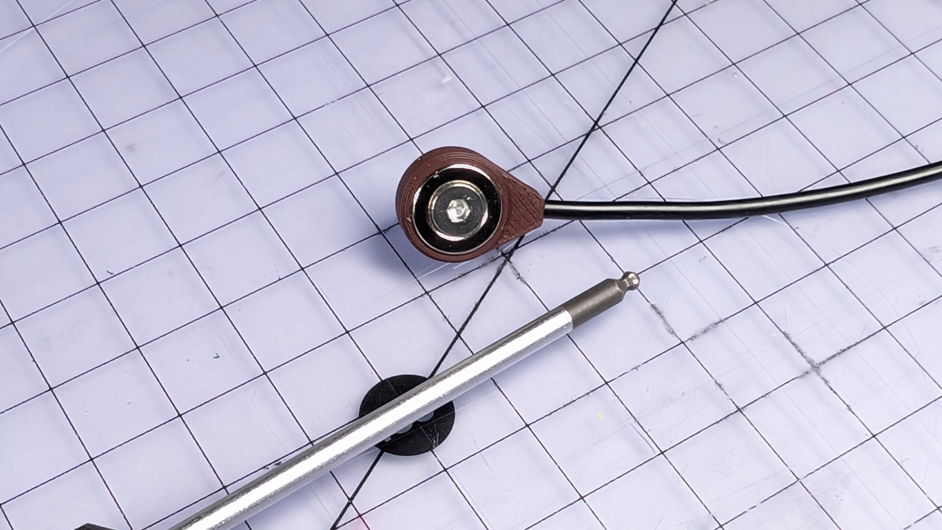
The bolt will stick out at the back. If you want to finish it nicely, you can add a knurled M3 nut or thumbwheel. I did.
Your wires are now prepped for soldering to the trailing socket. It doesn't matter which wire goes to which pole, and I'm not going to walk you through soldering or heatshrinking wires. There are plenty of guides out there for that.
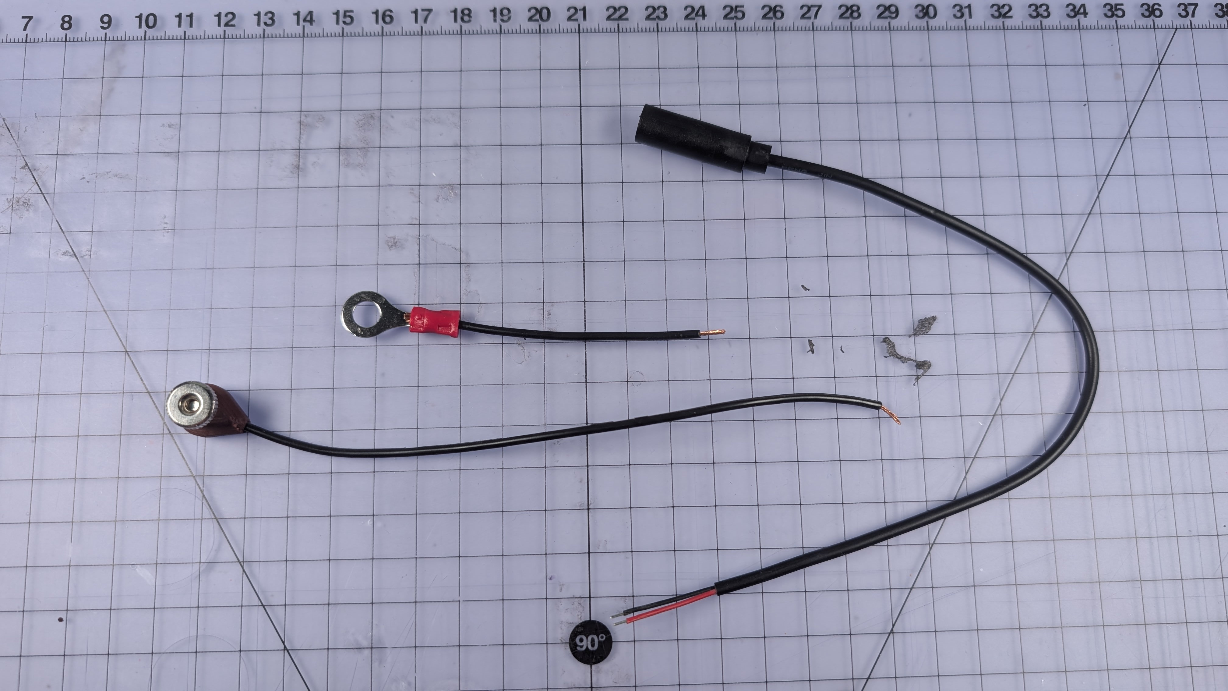
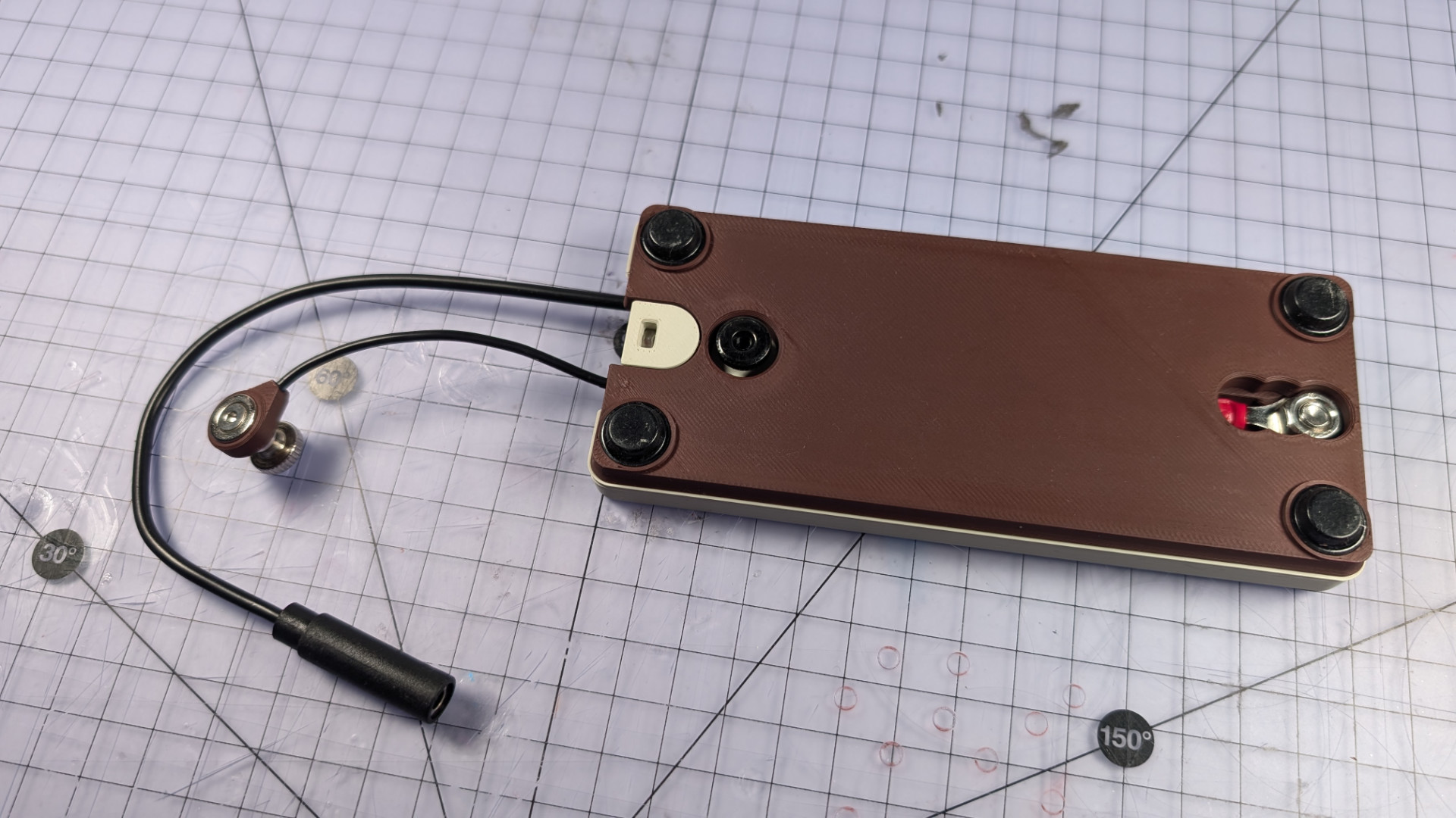
When you're done, it should look like this:
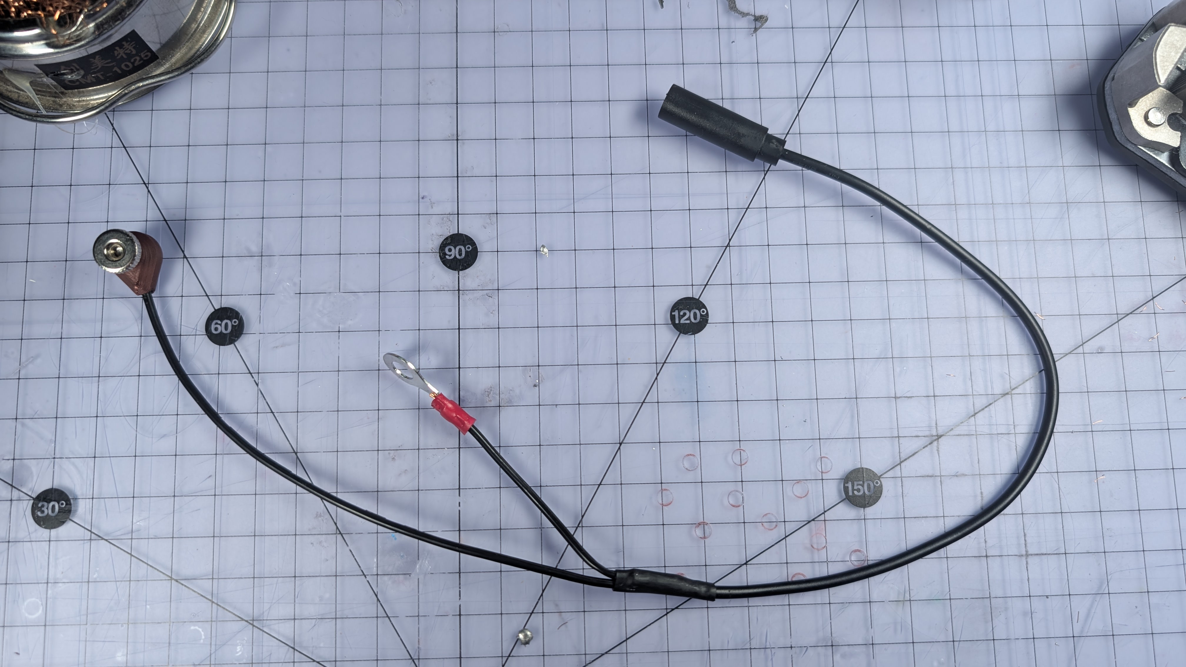
Maybe test it for continuity with a multimeter and a mono patch lead.
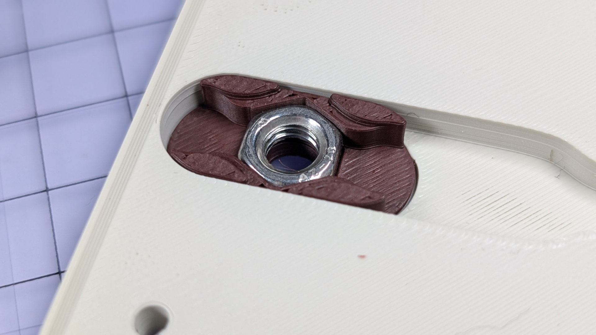
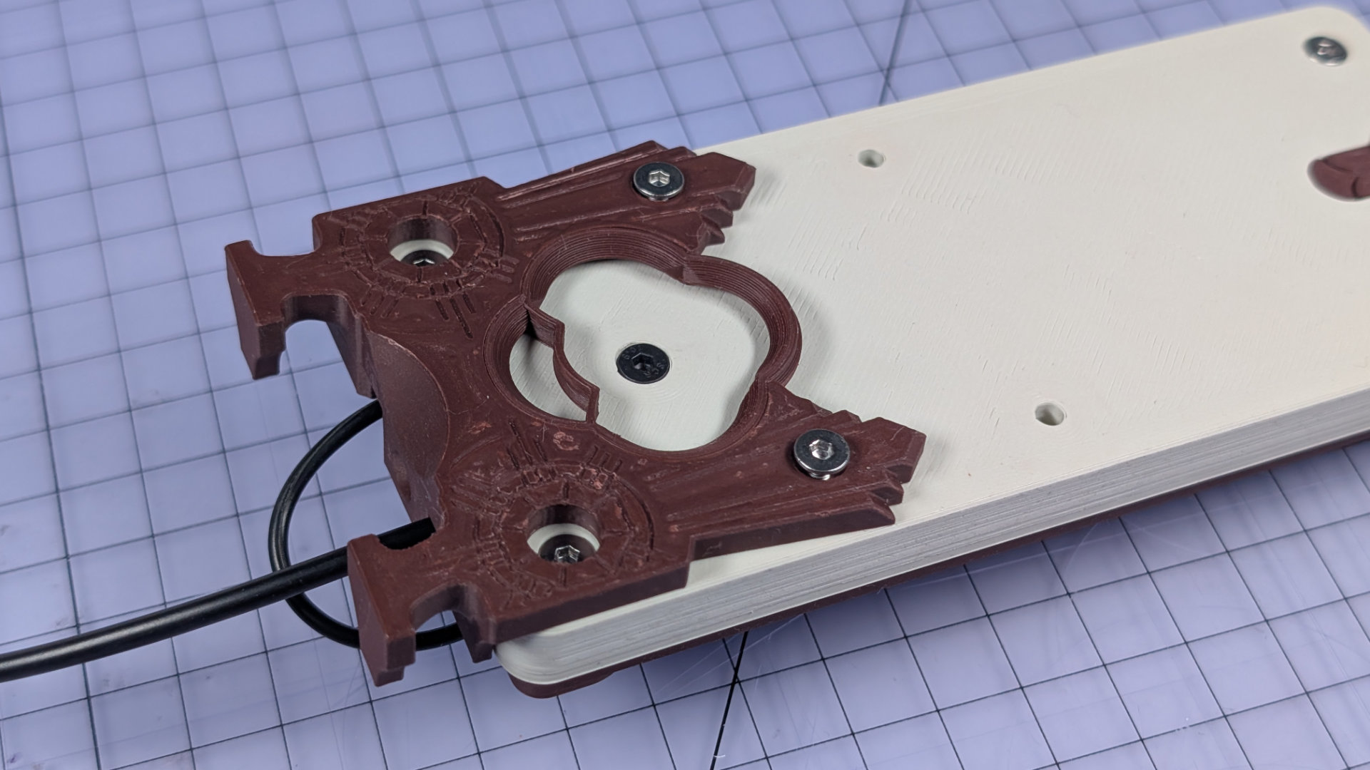
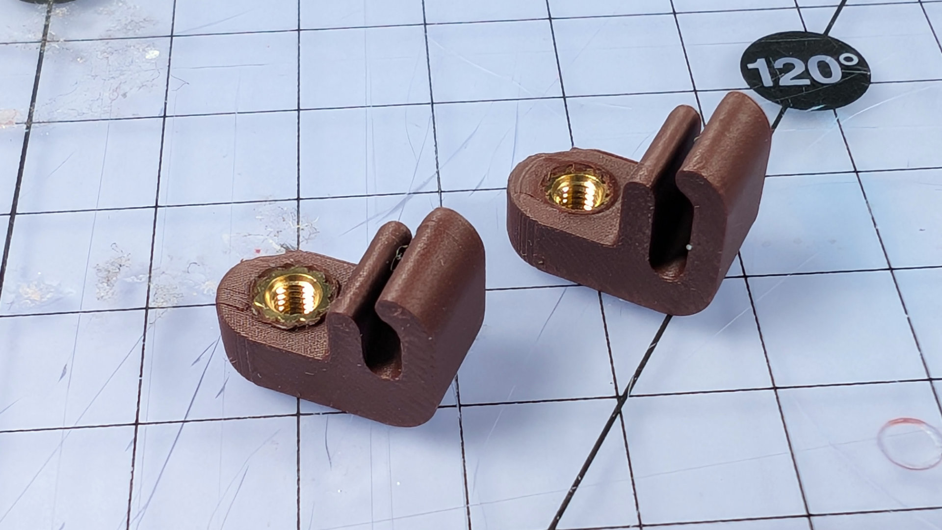
Install Flip Chip & Magnet Park
To accommodate different spoon lengths, there are two different flip chips, allowing three different positions for the front contact.
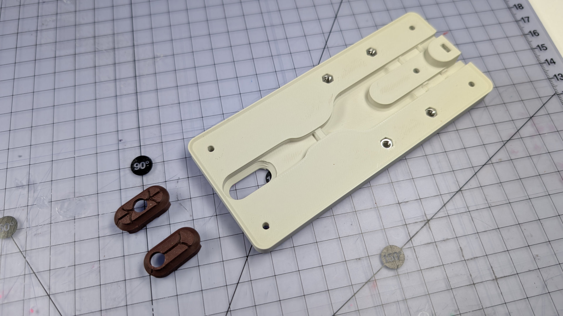
Take your preferred flip chip and push it into the underside of the baseplate.
Now embed an M6 half-nut in it. A full height hex nut will sit too tall in there; this one has to be a half-nut.
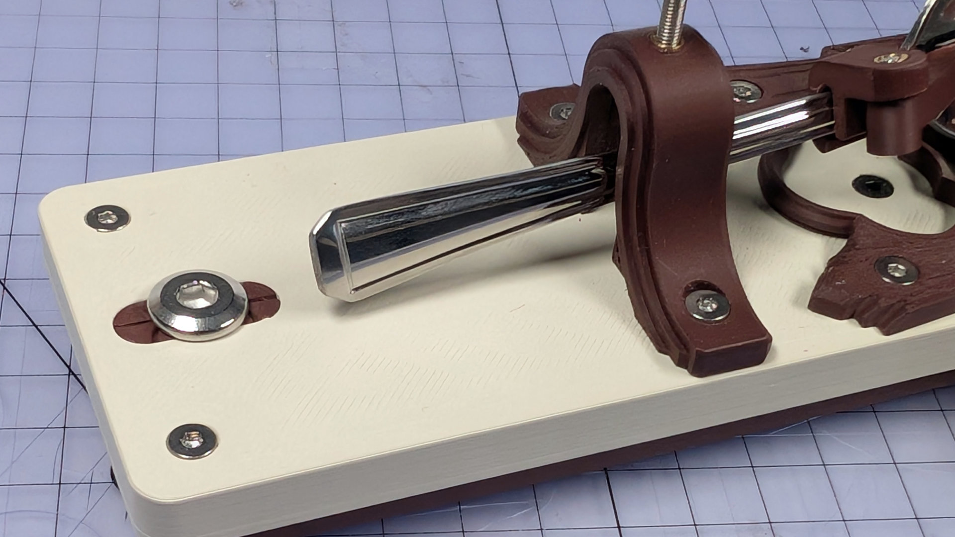
With a 4mm hex key, tighten the M6x12mm front contact bolt from above, to pull the nut tightly into the chip, and the chip fully flush with the top surface of the baseplate.
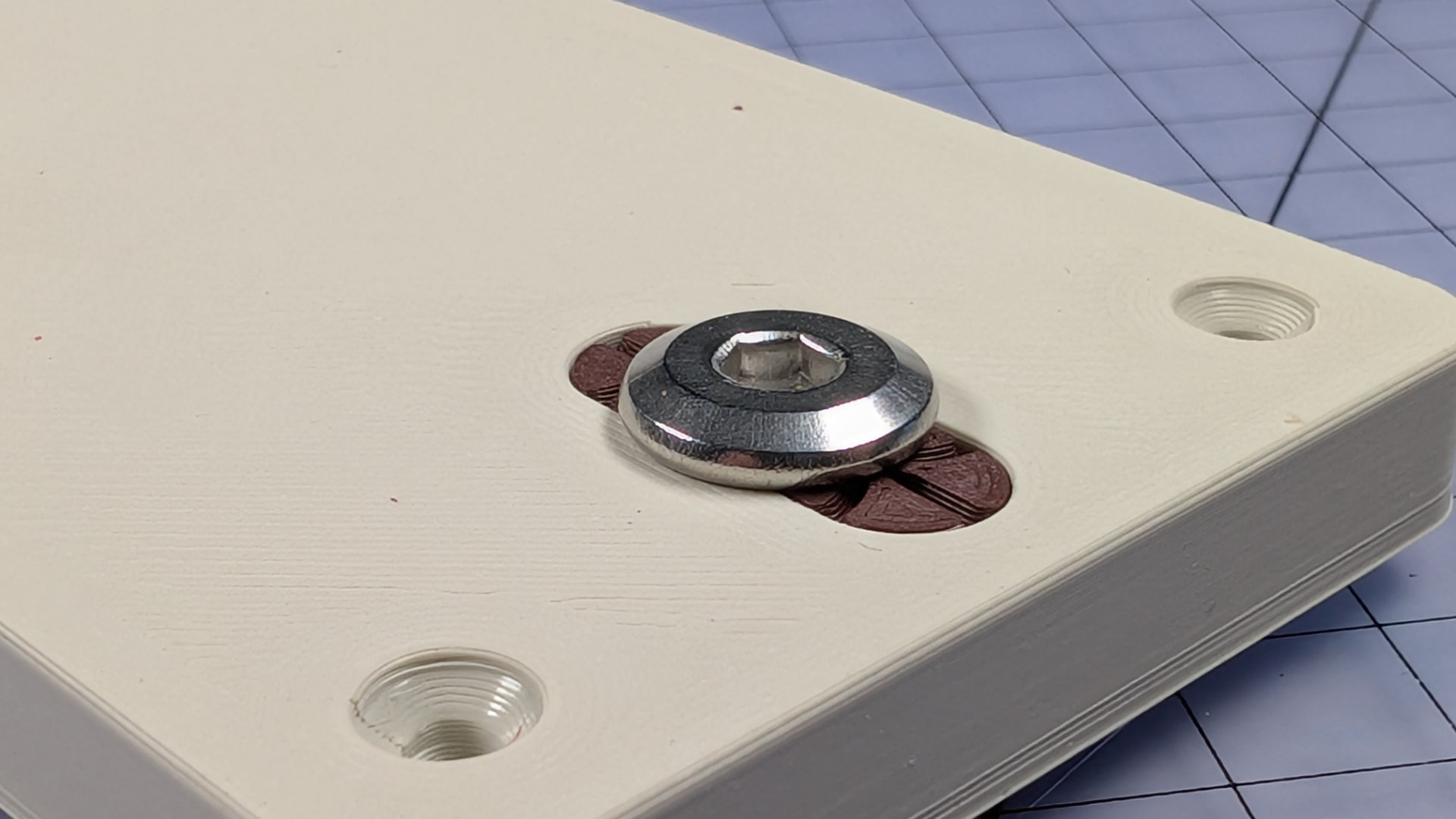
The flat lower surfaces of the flip chip should now be flush with the underside of the baseplate.
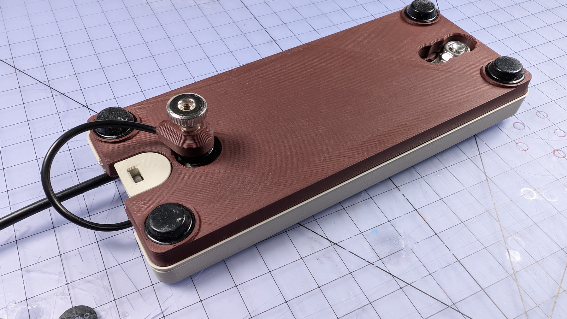
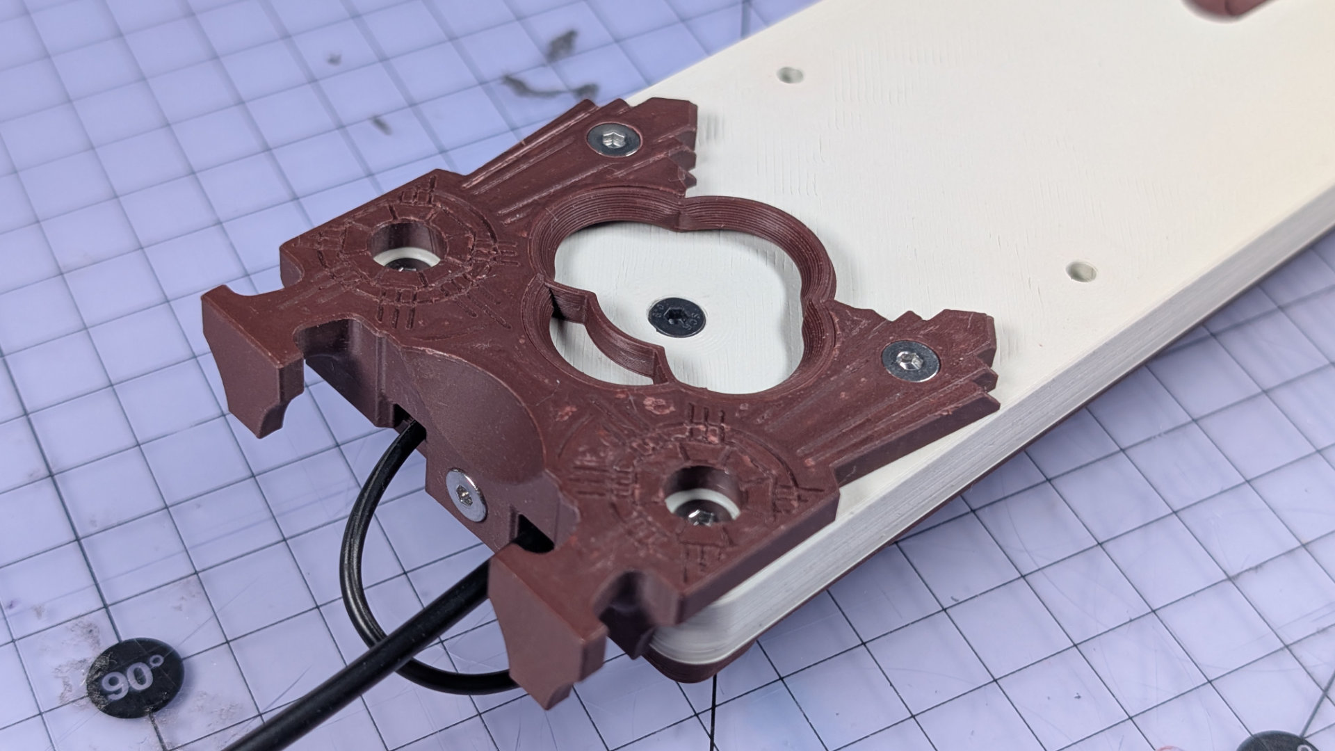
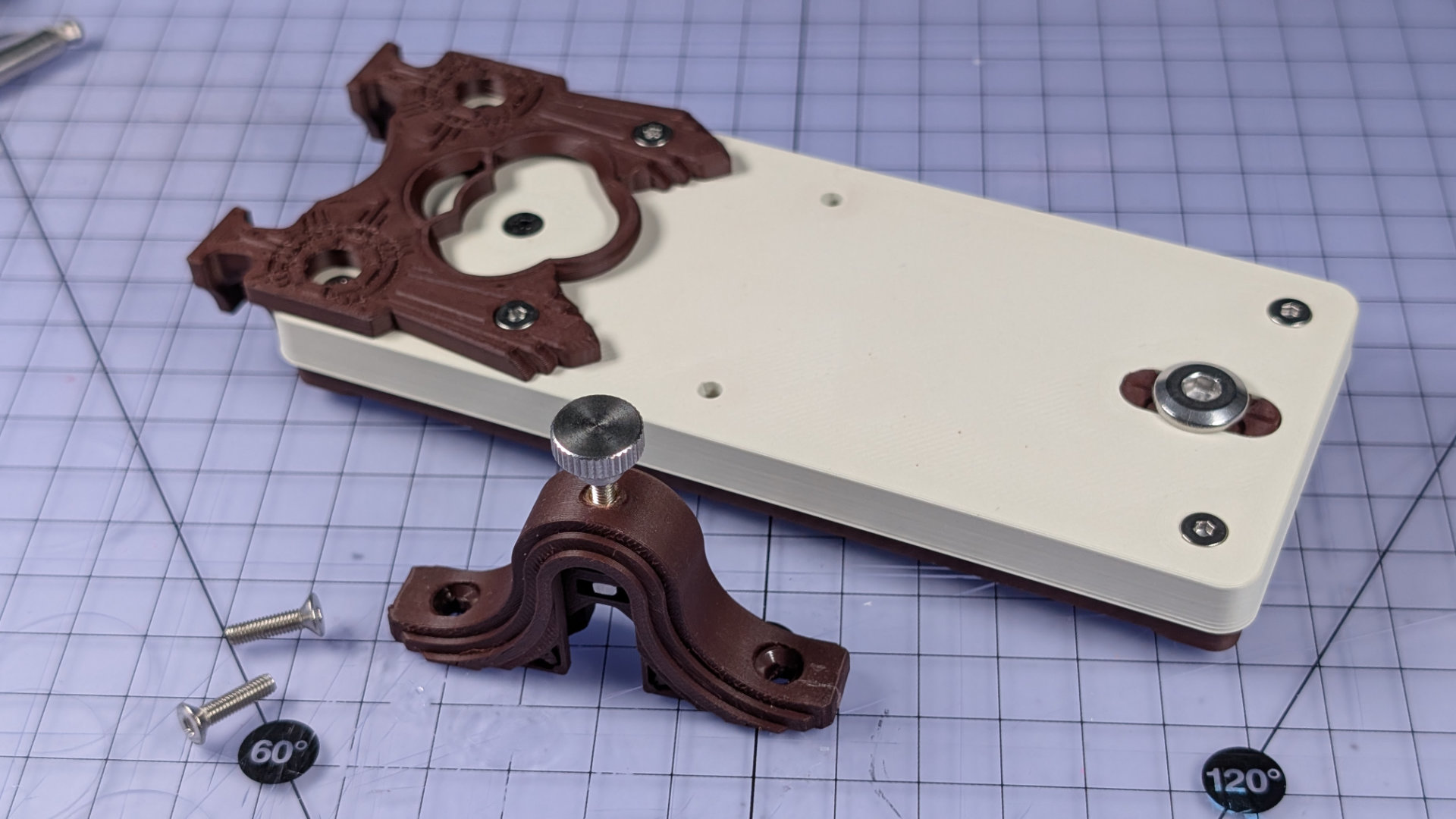
Magnet parking is optional, but nice to have. Just drop a suitably magnetisable M3x12mm fixing in the rear centre hole of the baseplate, then finish it with a corresponding thumbwheel. Stainless steel won't work, and that's why these two fixings are carbon steel with a black oxide finish.
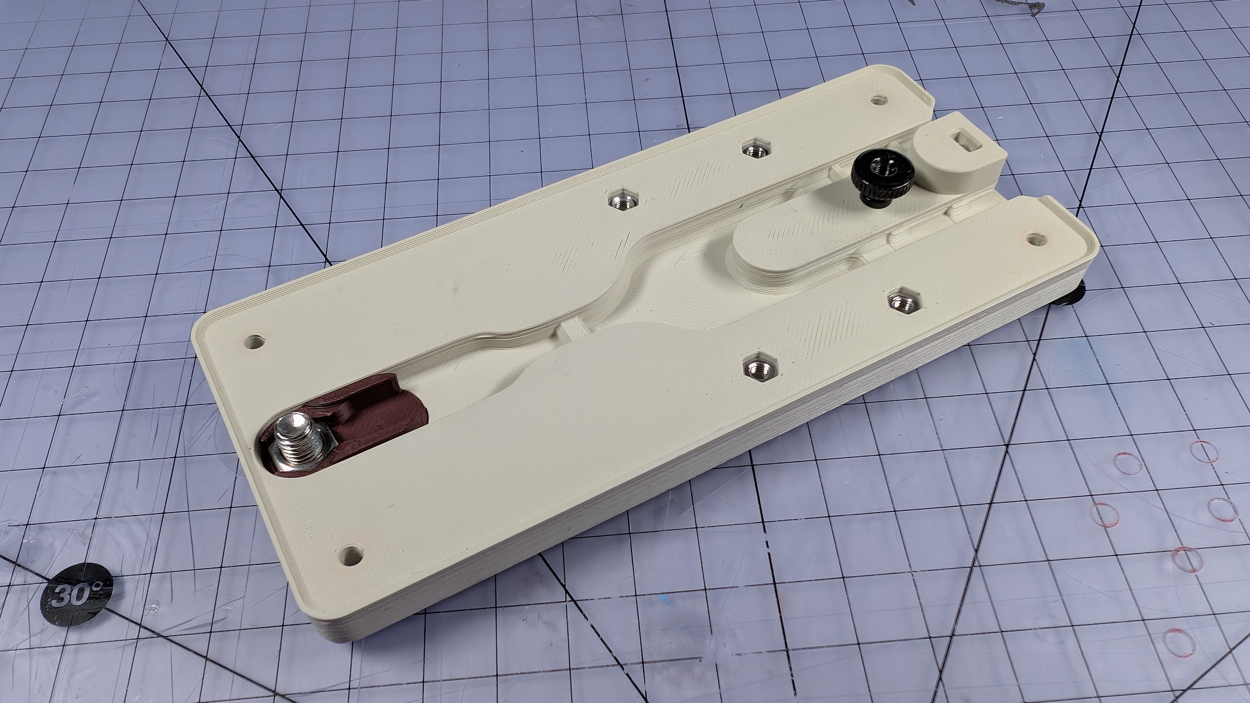
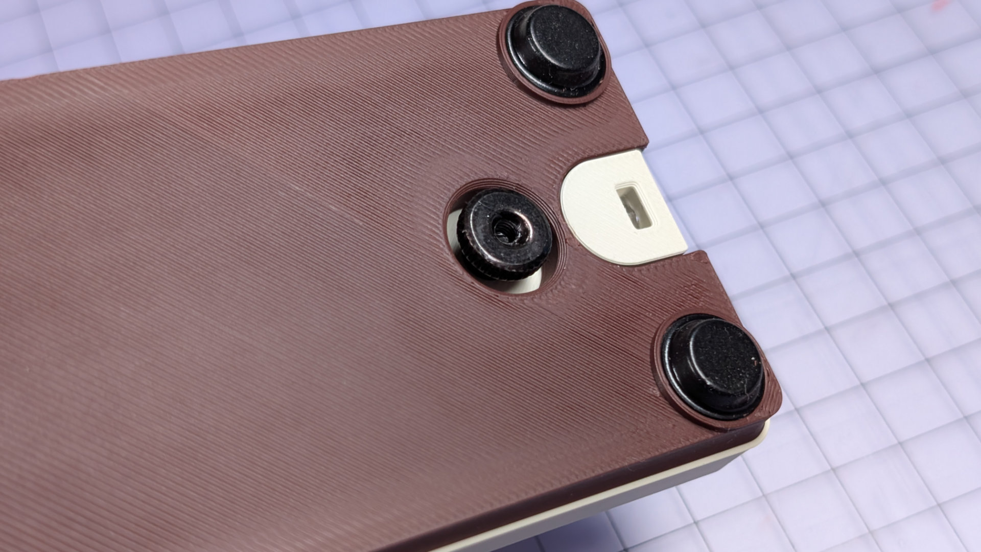
The hole in the bottom cover is clearance for the thumbwheel. The thumbwheel and screw can keep the magnetic contact out of the way, whichever side of the key you're working on. I added this feature because without something else to cling to, the contact kept grabbing my tools.
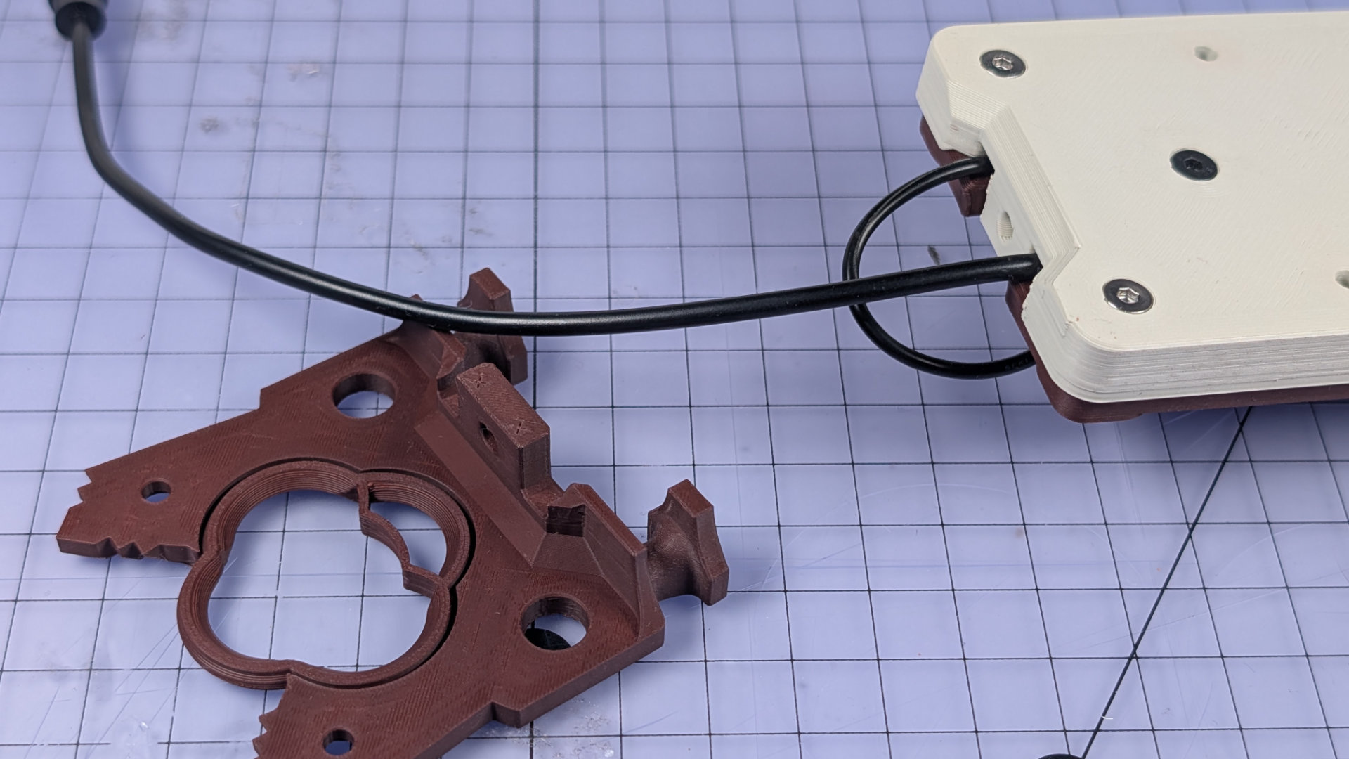
Install Wiring
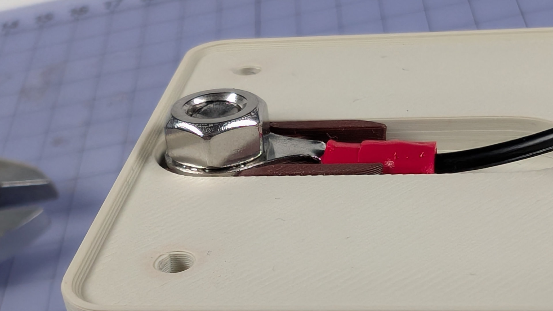
Place the ring crimp over the front contact bolt, oriented so the crimp body sits down in the baseplate channel rather than above it.
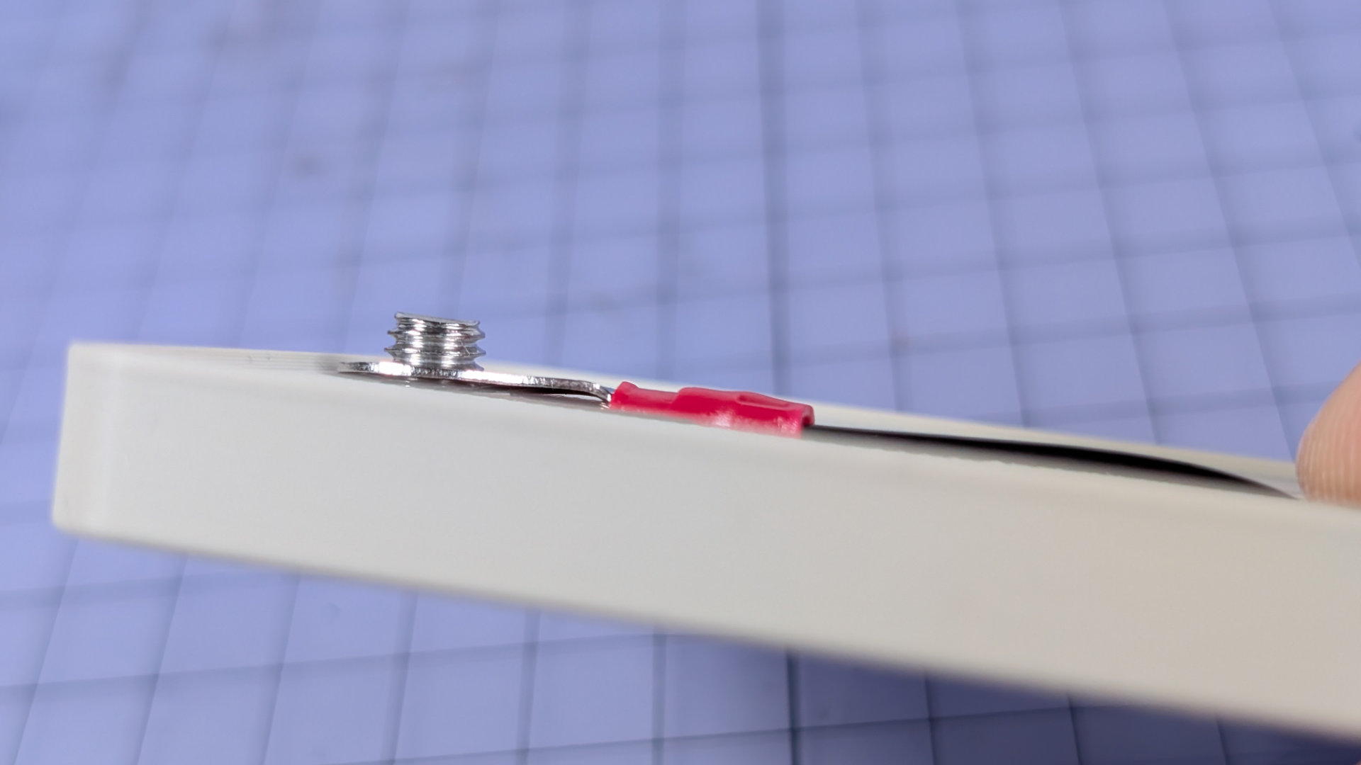
Lock it down with a second M6 nut. If the first nut in the flip chip is a half-nut, the end of the crimp terminal should now sit flush inside the chip. You might notice the second nut I've used here is a full height one. While a half-nut is better, a full one is okay here. When you attach the bottom, it will still just about clear everything with some gentle squishing.
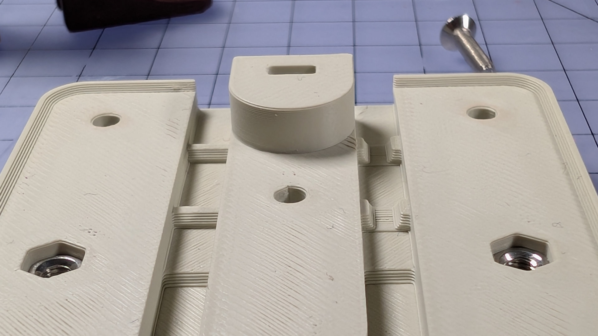
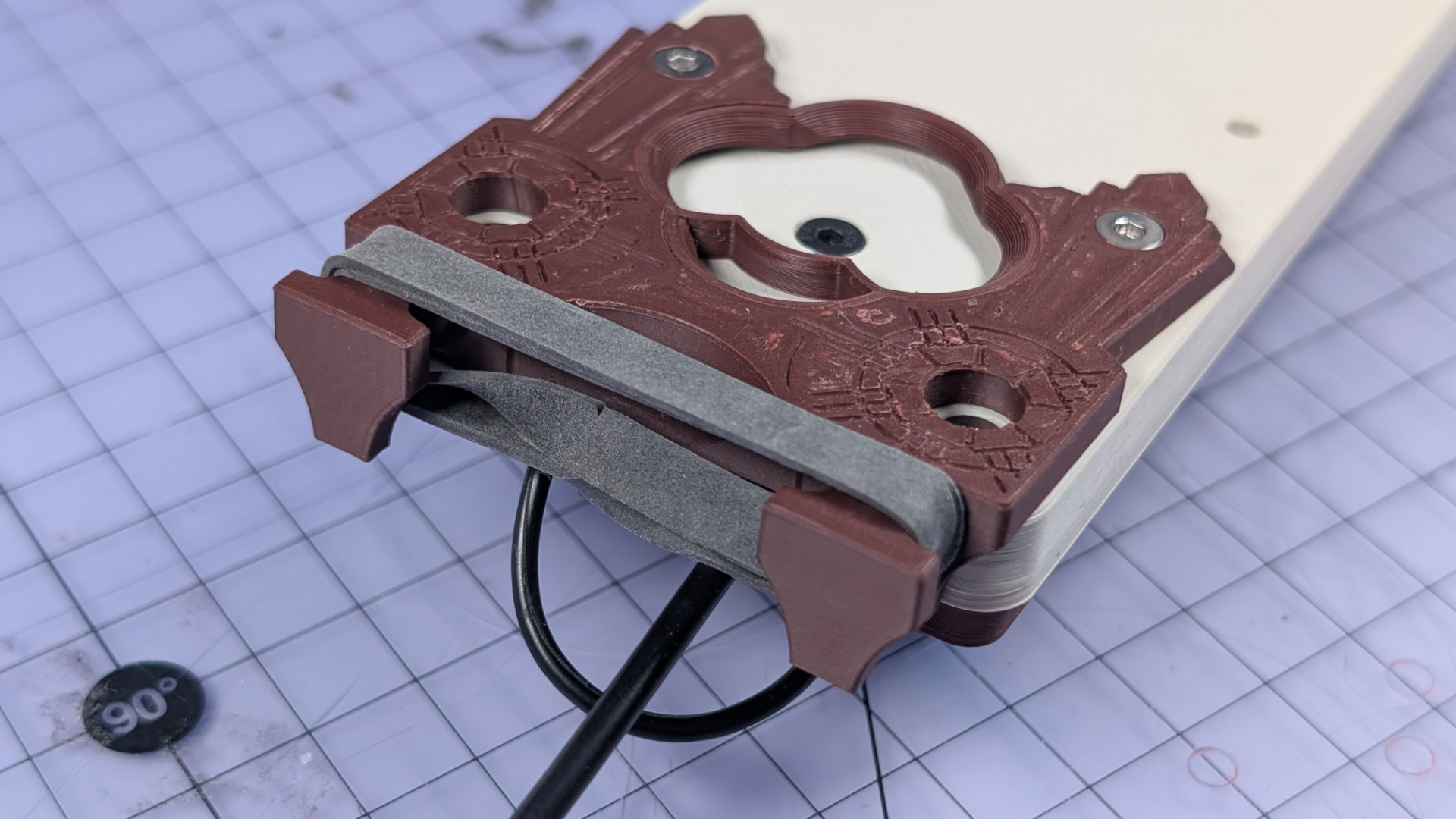
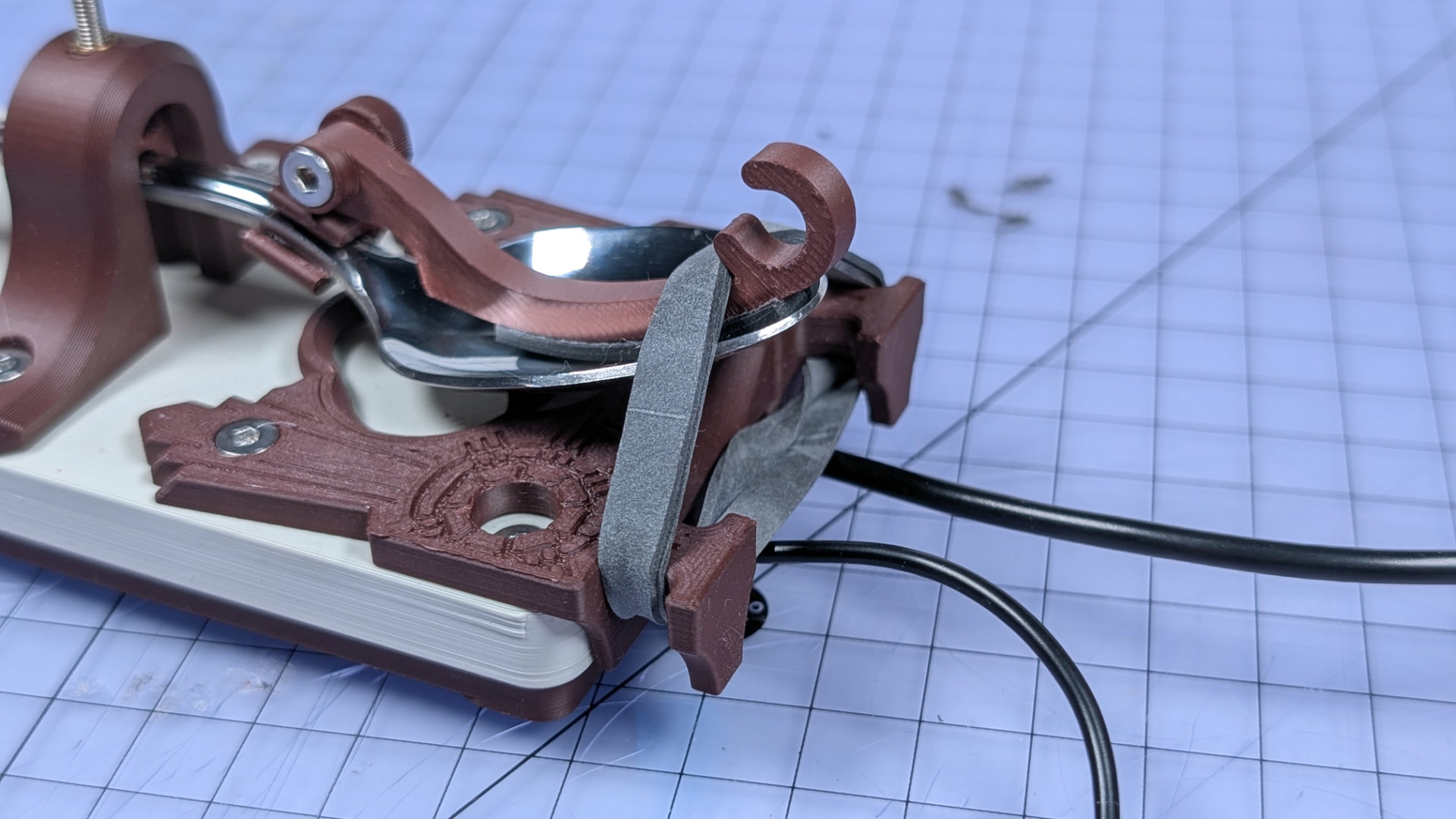
Notice that the two wire channels at the back of the baseplate have different types of strain relief built in. Pictured below, the left channel is for the single magnetic contact wire. The right hand channel, with the strain relief profiles notched out, is for the much thicker mono socket cable.
Lay the wiring in the correct channels, and make sure the section of heatshrink sits far forward enough to be in the deeper central well. If the wiring gets boisterous, you can tape it down to make it behave.
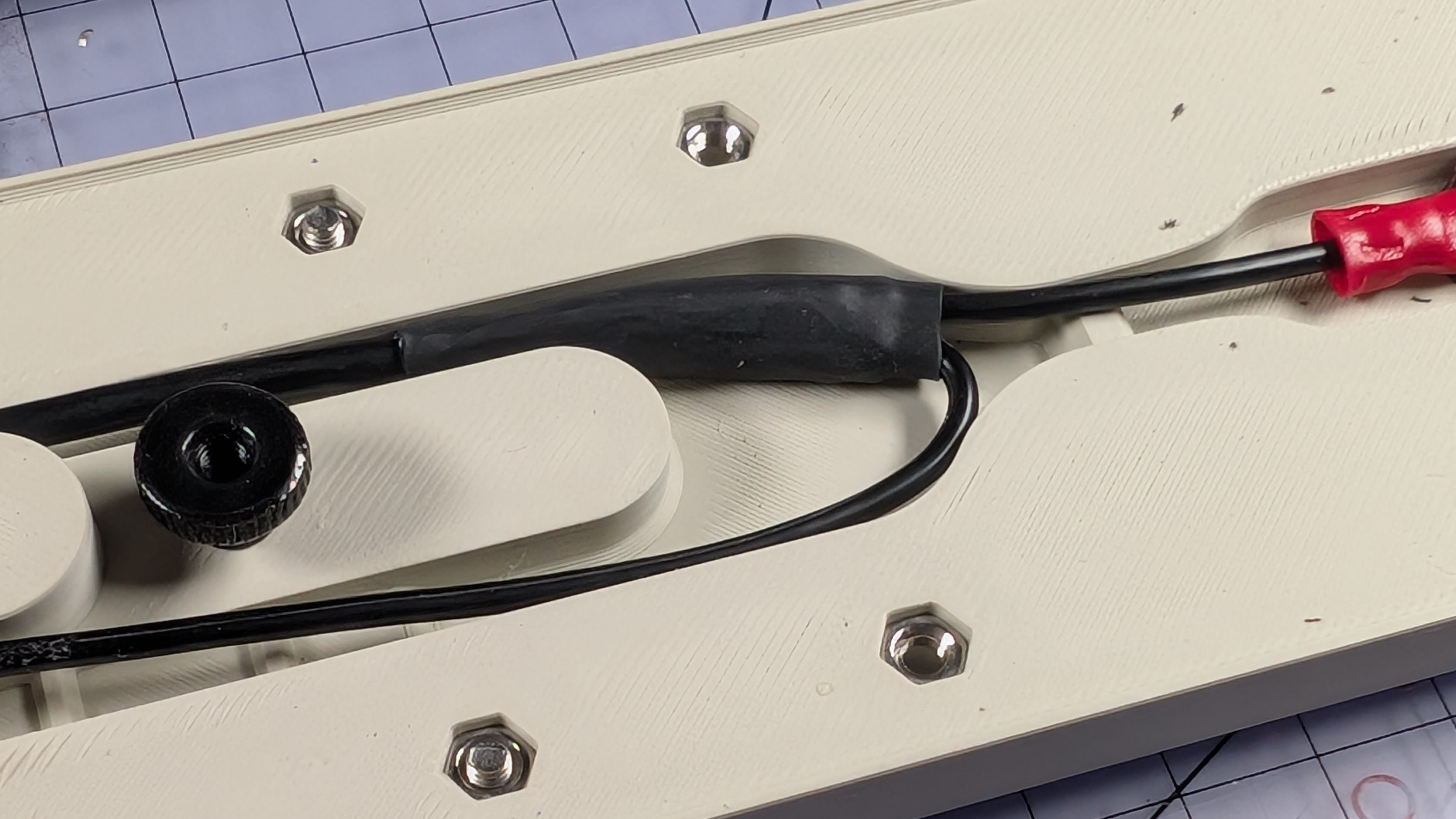
If you installed the front contact in the middle or rear positions, you might need to bunch wires up and let them squiggle around a bit in that central area. That's fine.
Now install the bottom cover.
You can test out the magnet parking too.
Install Spoon Plate, Elastic Band
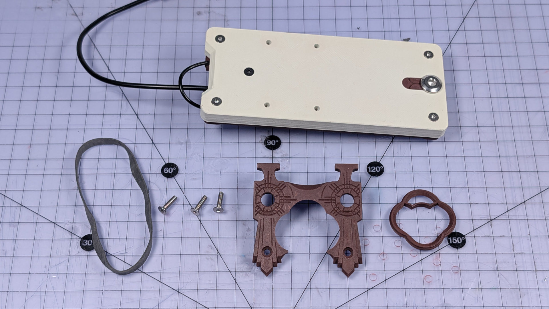
For this step, you need the spoon plate, one elastic band, three M3x12mm countersunk screws, and a bearing insert. There are three types of insert in the print files, but the one shown here seems to work best with most spoons.
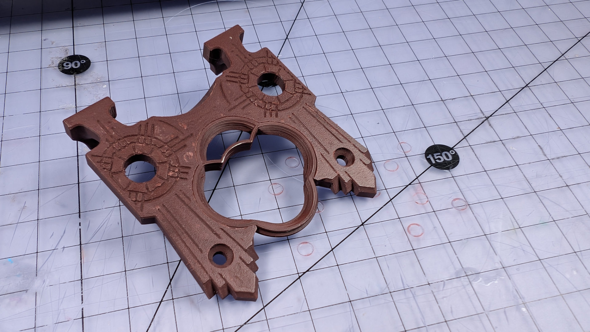
Push the insert into the corresponding socket of the spoon plate. If both are new prints, the plate should retain the insert by itself.
The rear end of the baseplate and underside of the spoon plate have corresponding geometry.
Slide the spoon plate into place, and insert the two front screws loosely. Don't tighten them all the way yet.
Install the rear screw, and tighten that fully. As long as it's M3x12mm, the hole in the baseplate is depthed to prevent it from crushing the spoon plate. A shorter screw or one with a differently shaped head might damage it, splitting layers apart and breaking the bottom off that tab.
Once the rear screw is in, tighten the front ones.
Take your elastic band, and put a twist in to double it up. Stretch it over the two hooks on the spoon plate.
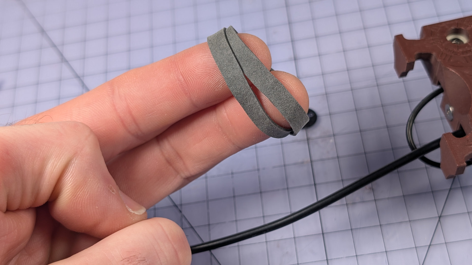
With some fettling, you can put all the twisty bits in the lower portion of the band, and have the topmost strands sit flat and smooth. Doing this will make the key look nicer later on.
Install Travel Adjuster
The threadlock on the travel adjuster should be dry by now. Treat yourself to some congratulatory fiddling.
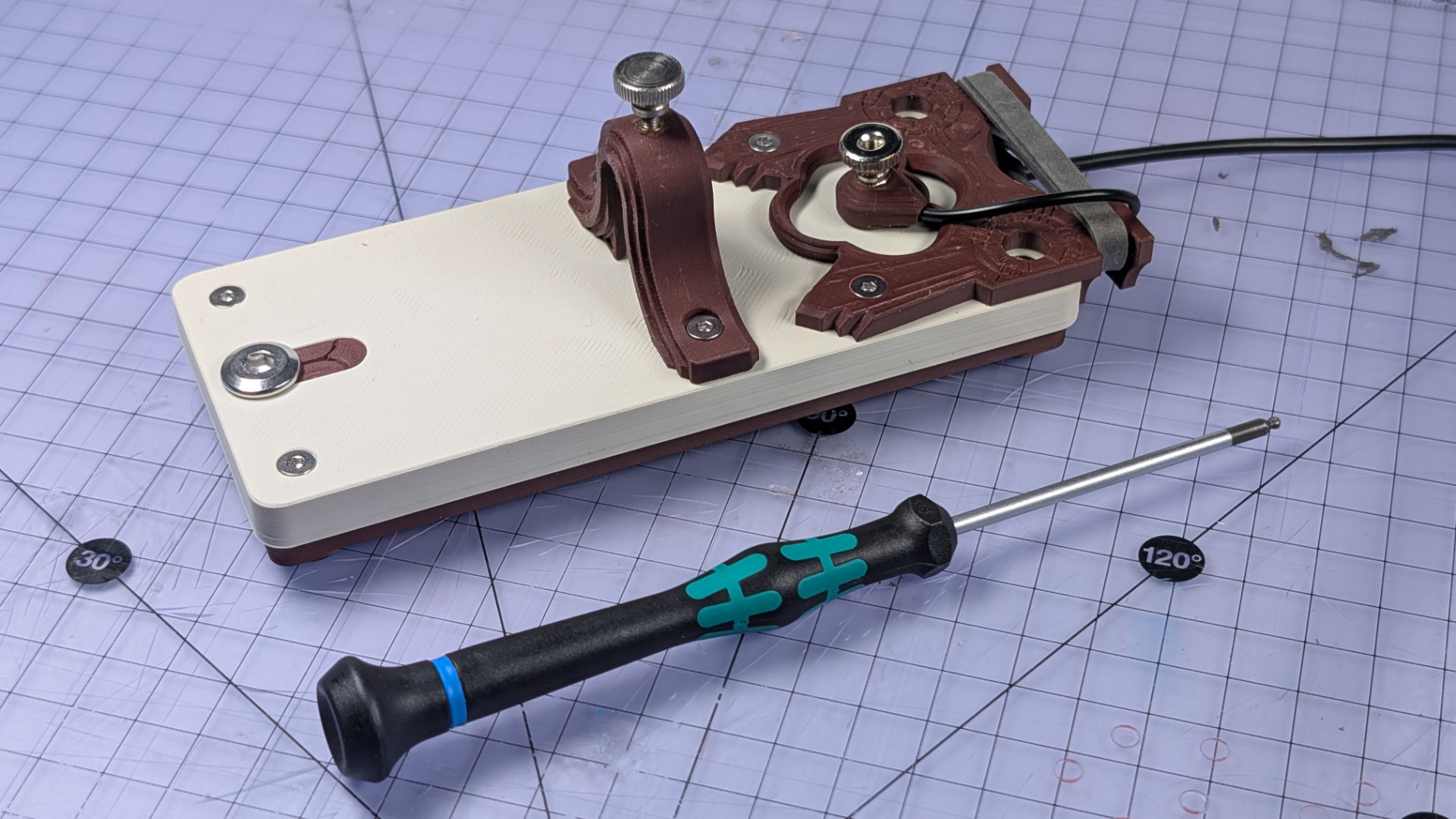
It should be obvious which two holes it attaches to, and how. Be very careful not to over-tighten the screws; the torque specification for these two fixings is zero uggadugs. The print orientation that makes the travel adjuster run smoothly also puts the mounting holes between layer lines, so if you over-tighten the screws, the countersunk heads could easily split the part.
The image above shows a travel adjuster I did that to, and the silicone glue repair I gave it is visible on the right. Below is a properly installed one. An L-shaped hex key can give too much leverage for this step. I find a straight 2mm hex driver like the one pictured gives just enough force to avoid over-torquing.
Spoon Hook Spoon
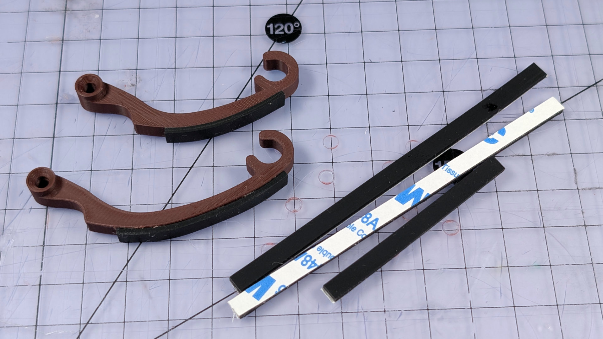
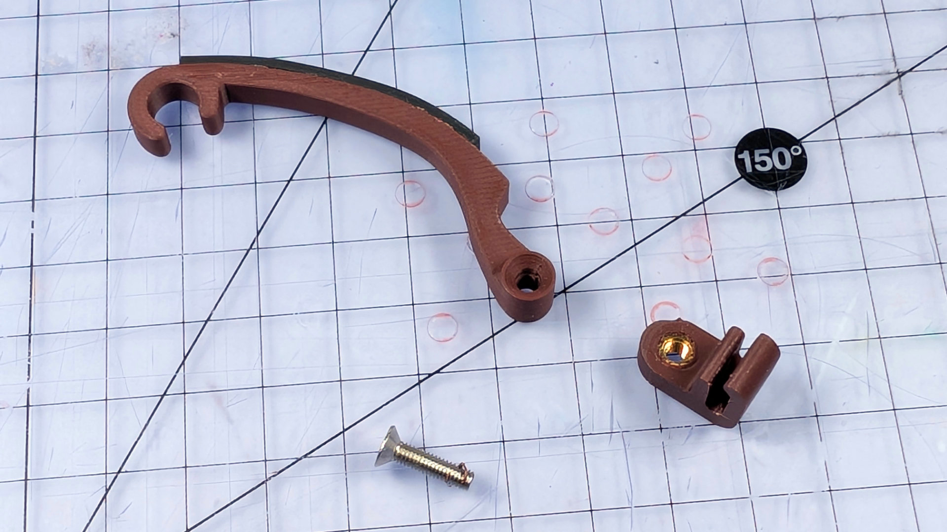
Nearly done. You just need to hook a spoon and jam it in. The spoon hook is made of a hook and clip, which get bolted together. There are two hook lengths and two clip widths, to suit different types of teaspoon. You could also make your own by modifying the .step files.
The clips print in the orientation shown above, and need heatset M3 inserts. I did start out with several versions that used M3 nuts instead, but was never happy with any of them. This brass insert design is better by miles.
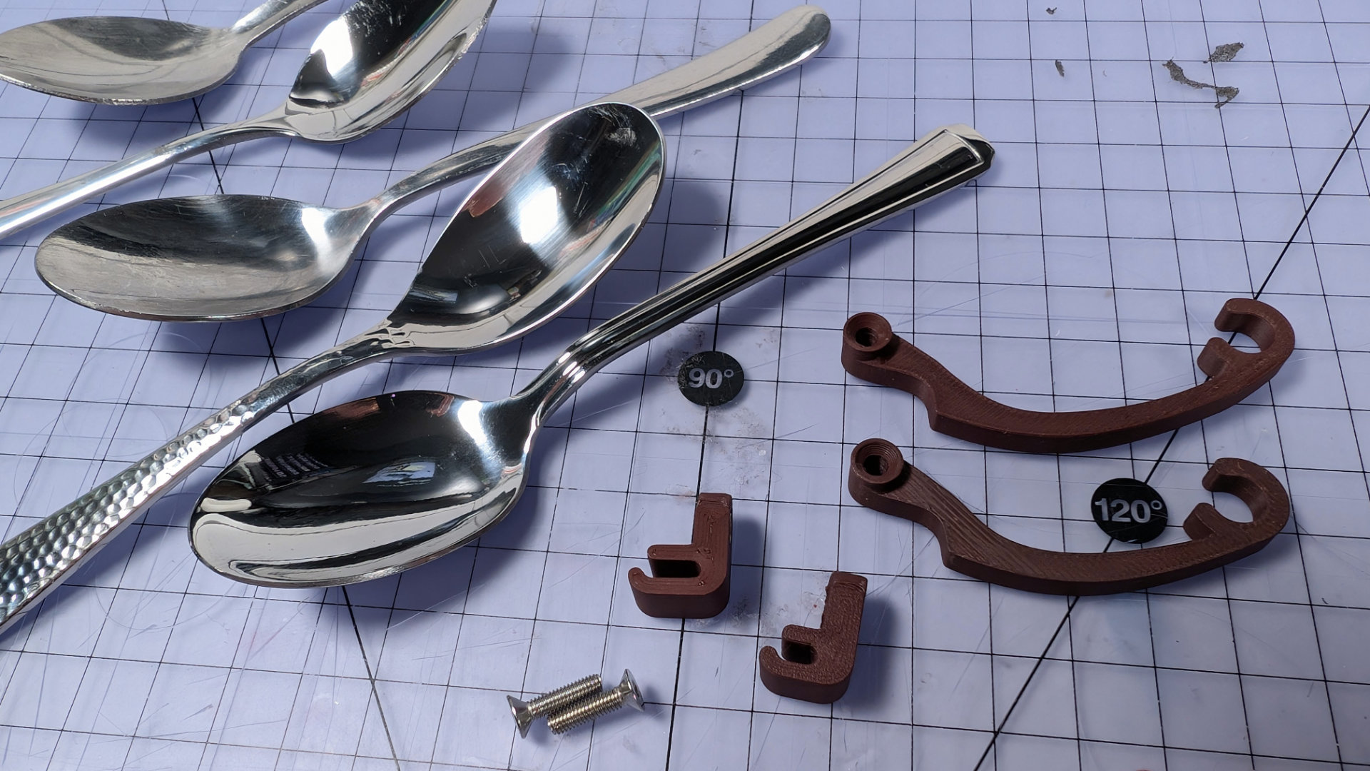
Here are the two widths of clip on a variety of teaspoons. The type of click the key makes depends very much on the spoon, and I find some feel much better to use than others.
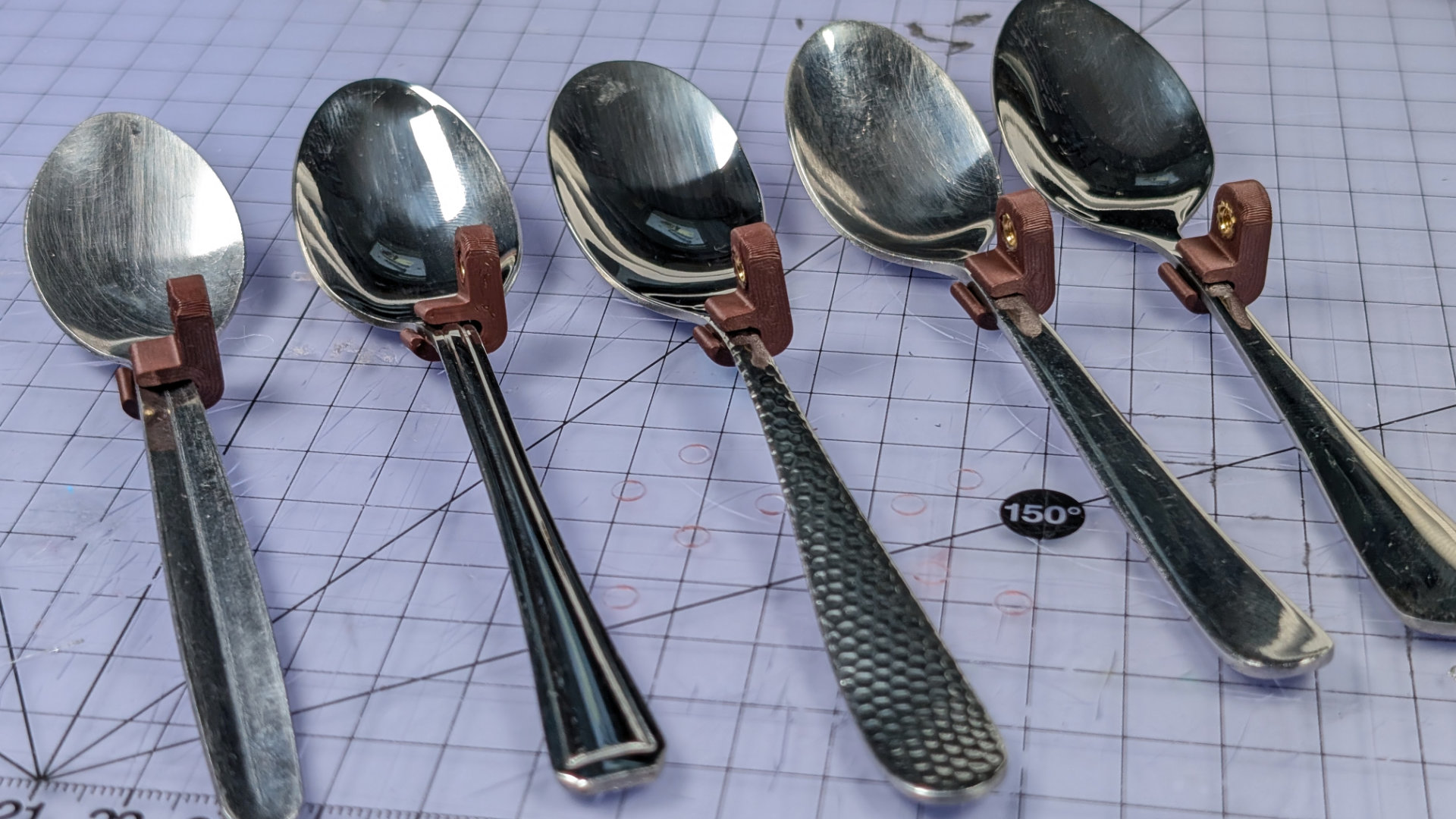
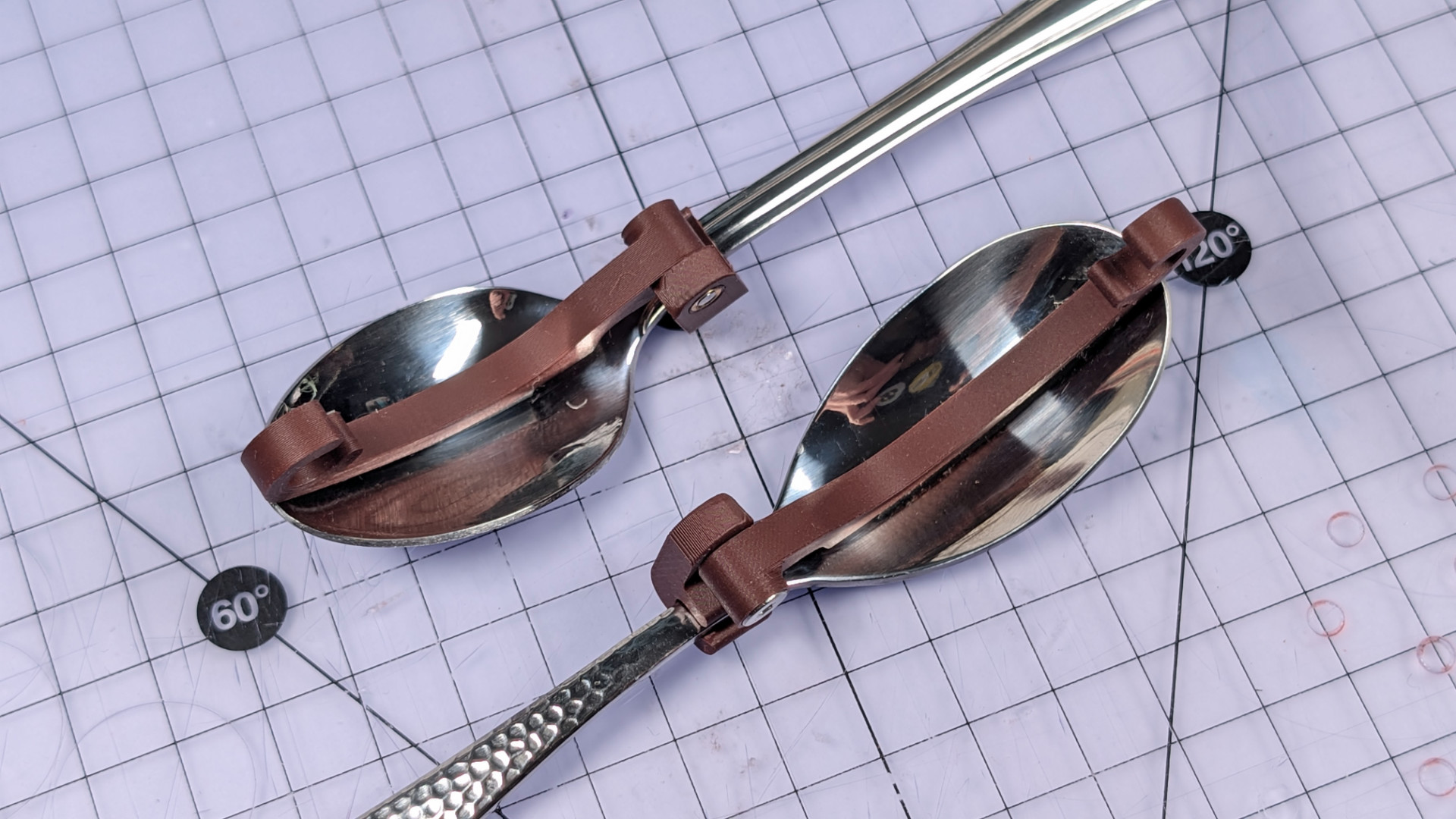
To give an example of hooks, the little stamped art deco spoon below needs the short hook with the wide clip. The hammer-textured spoon has a more elongated, teardrop head with a thinner neck, so works better with the long hook and narrow clip.
Optionally, you can slice a 5mm strip of adhesive rubber to pad the bottom of your hook. This makes it a bit less prone to migrating around in the head of the spoon, though the rubber pad can get wonky over time (to be fair, my rubber sheet didn't say VHB on it, and came from Jeff's Automated Late-Stage Captalism Monopoly Warehouse. If a retailer sells everything, anyone can get away with printing "3M" on their products).
There might be better ways of attaching rubber to a hook. If you have one of those fancy-pants multi-material printers, you could even redesign the hook with integrated TPU pads.
To assemble the hook, orient your parts like this. They need one more M3x12mm machine screw.
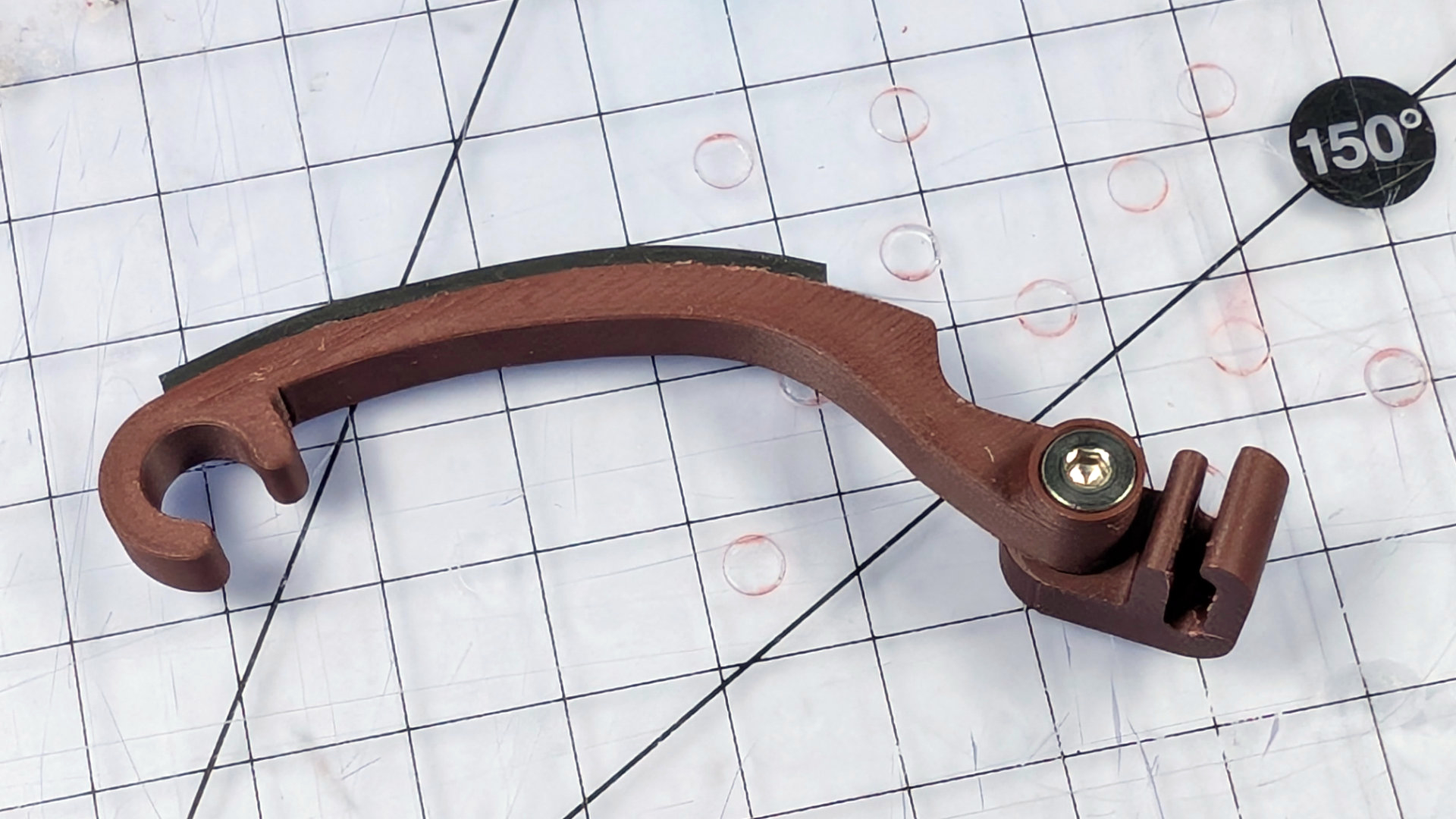
Bolt it together like this. Don't leave it loose.
Clip it onto the spoon like so.

The parts are designed so turning the hook down into position from above keeps the fixing tight. No harm in making sure with a hex driver too.
Next, double check the hook length is right. Whoops. The clip sitting all the way back like that might foul the travel adjuster.
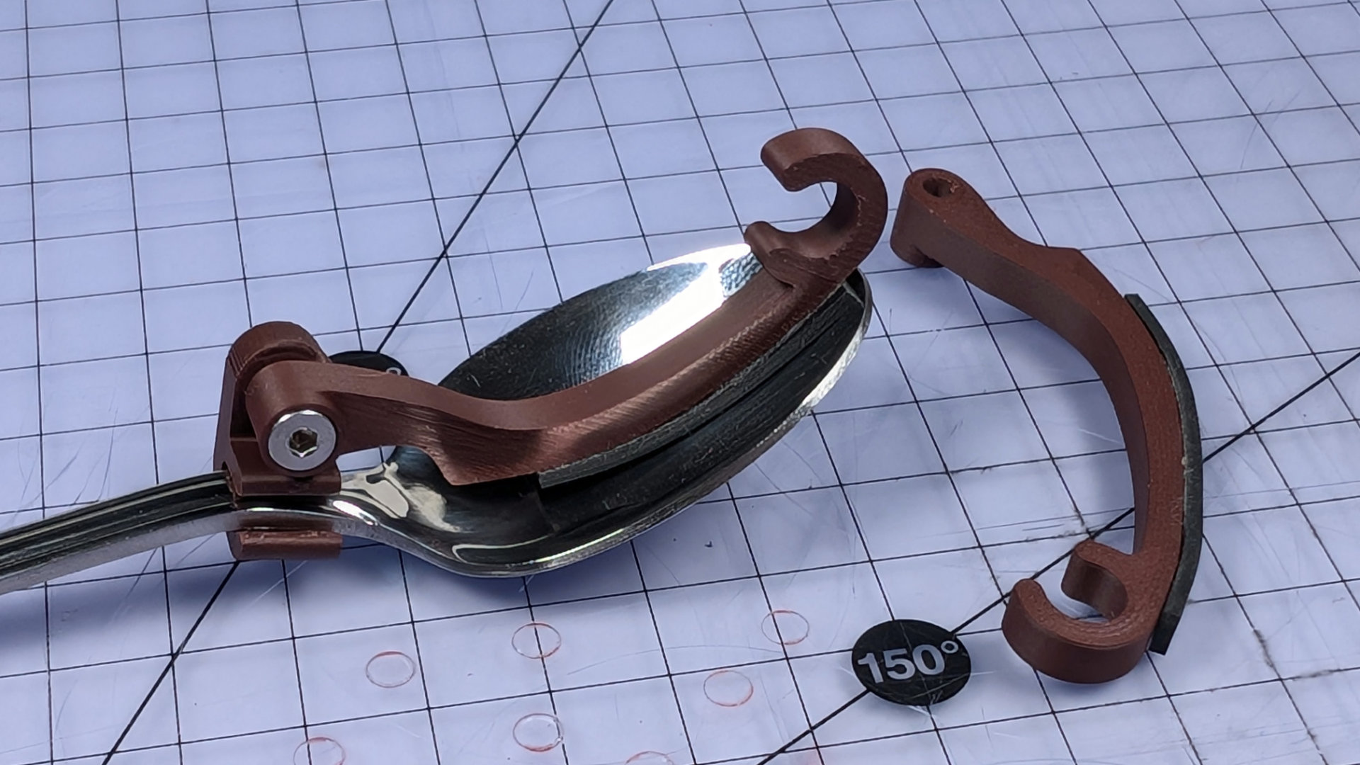
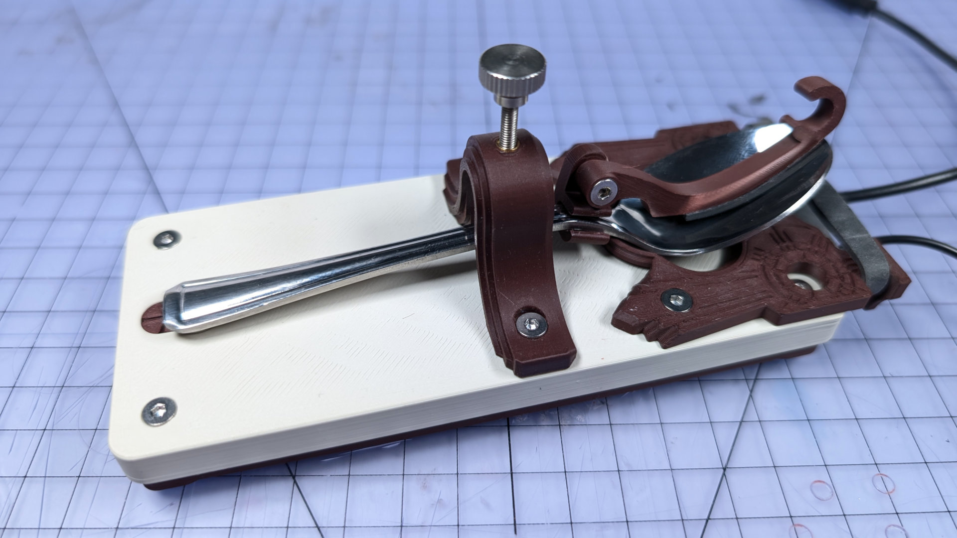
Better. Now we're ready for some spooning!
Open up the travel adjuster as far as it needs to go for the thin end of your spoon to sidle on through. If your spoon is too big, you might just need to remove the travel adjuster then reinstall it with the spoon in place. If the neck of your spoon is wider than 10mm, find a different spoon, or design and print a wider travel adjuster.
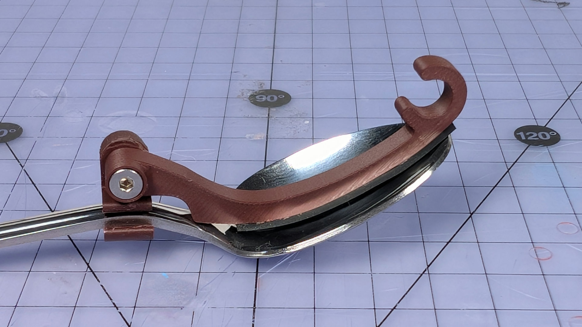
Tenderly lay your spoon on the bearing insert.
(It's late and I'm tired. The colour temperature of these photos is all over the place).
The hook has a C shape at its tip. Pull the upper parts of the elastic band over the hook, placing them beyond the tab that forms the short part of the C.
Now lift the lower spans of elastic over the hook, placing them down inside the C. If they're very taught, you can even up the tension first and create some slack, by yanking on the upper sections either side of the hook.
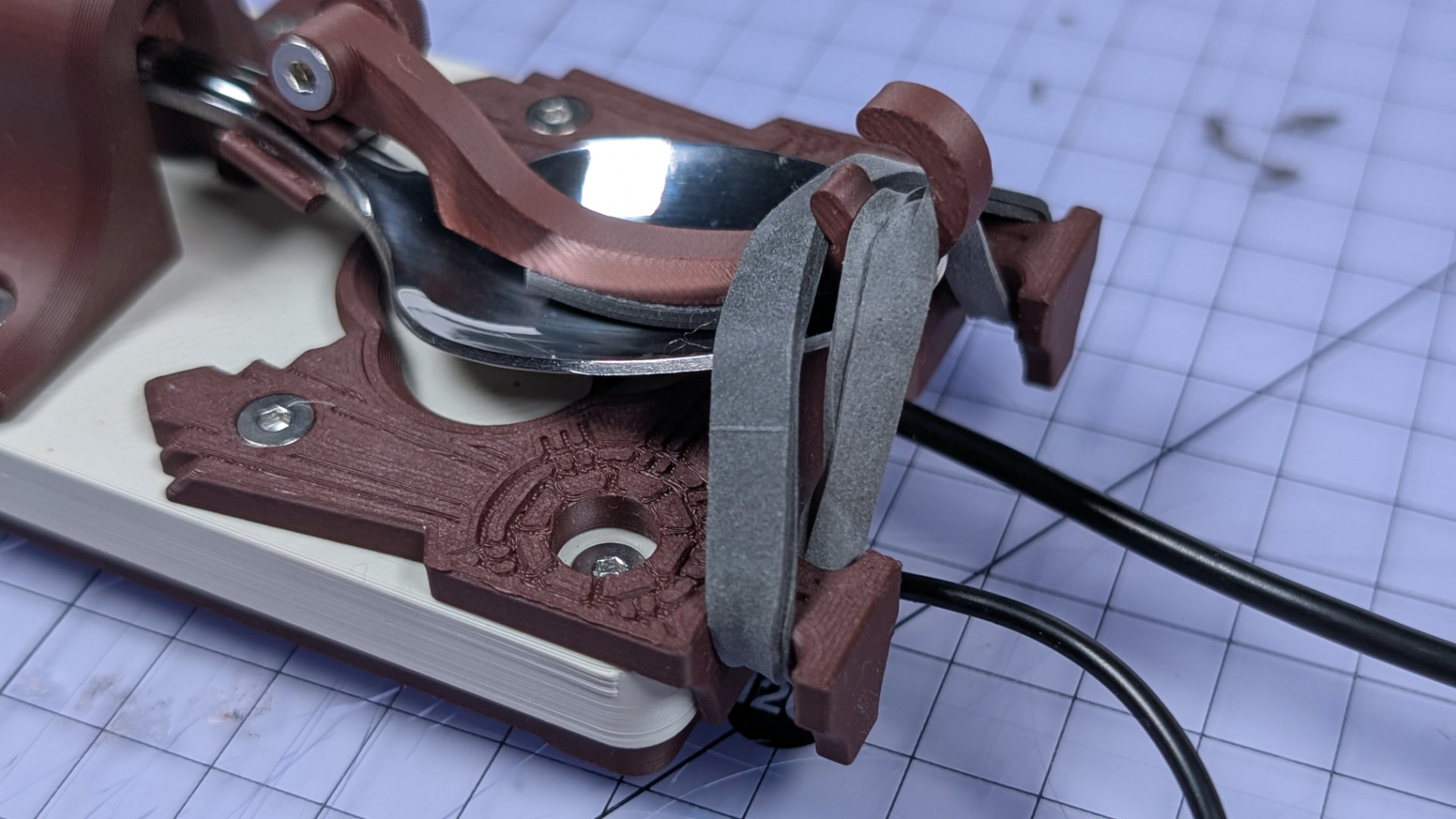
With the lower spans of elastic in the hook, now pop the upper sections on top of them, inside the C.
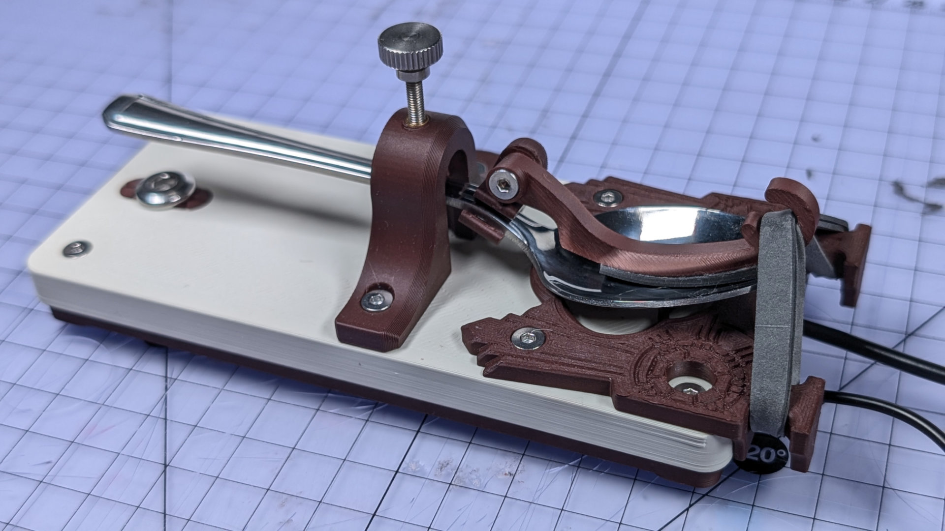
You won't set any morse code words-per-minute records with that spoon handle flapping around all the way up there. Adjust travel downward to something more sensible.
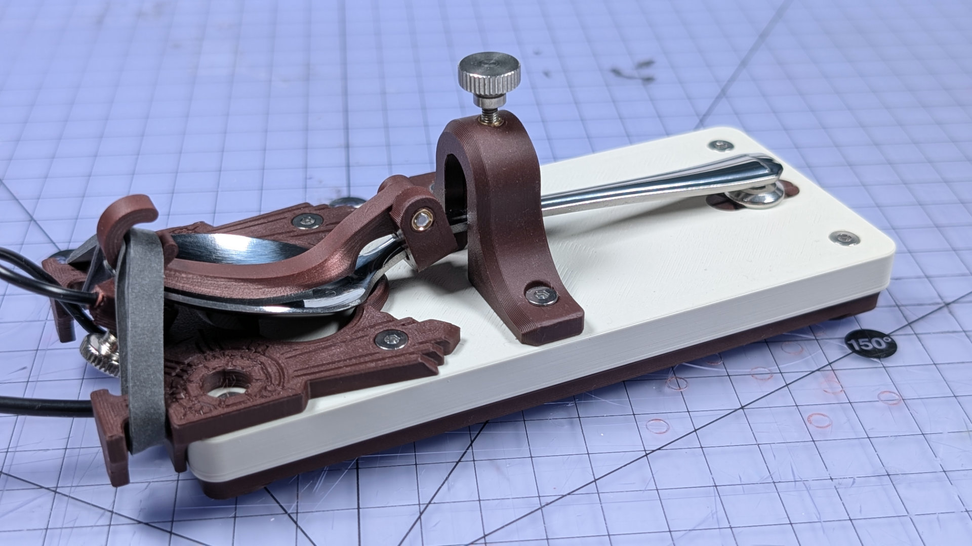
That's it! Well done, you now have a completed Teaspoon Telegraph, ready to connect up. There are some pointers on doing that in the Teaspoon Telegraph Manual, or you can head back to teaspoontx.